A 50 m³ thermal store held at 80 °C can lose roughly 1.7% of its usable heat every day through its shell, nozzles, supports, and manway. Nobody draws a kilowatt-hour. The tank still looks perfect. Over a year, that silent leak can erase a meaningful share of the savings the project was built to capture.
Most buyers specify volume and shell material with care, then accept a generic “100 mm insulation” line item. Thermal storage tank insulation deserves more. It’s the engineered system (material, thickness, vapor control, jacketing, and detailing) that decides whether the tank performs as modelled or quietly underperforms for decades.
This guide covers the calculation, geometry, material choice for hot and chilled duty, thickness economics, and detailing for outdoor service. Thermal store insulation isn’t a blanket you add at the end; it’s a system you design with the tank. For the vessel itself, start with our complete thermal store tank guide.
What Is Thermal Storage Tank Insulation?
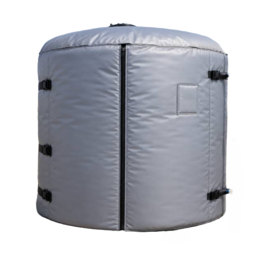
Thermal storage tank insulation is the engineered layer, or layered system, that slows heat transfer between a stored hot or chilled medium and the surrounding air or ground. It combines insulation material, thickness, vapor control, jacketing, and detailing at supports and penetrations to limit standby heat loss and prevent moisture damage.
Think of it as three jobs in one envelope. It limits standby heat loss, keeps outer surfaces safe to touch and above the dew point on chilled duty, and protects the steel shell from moisture that causes corrosion under insulation.
A material datasheet isn’t a specification. Mineral wool, polyurethane, and cellular glass are materials. The insulation system adds thickness, vapor retarder, jacketing, and details at every nozzle, manway, support, and penetration. A tank can have 200 mm of the right material and still fail because the top is bare or the jacketing stops above a support ring.
At proposal stage, ask each supplier to describe the full system and its heat-loss target, not just the thickness line. Get the scope in writing.
How Thermal Storage Tank Insulation Controls Standby Heat Loss
The core relationship is simple enough to check on one line:
Q = U × A × ΔT
Q is heat loss in watts. U is the overall heat-transfer coefficient in W/m²·K. A is the external surface area in m². ΔT is the tank-to-ambient temperature difference in kelvin.
Insulation works on U. For a plane layer, R = thickness ÷ λ, and U = 1 ÷ (R_insulation + R_surface). A 200 mm mineral wool layer with λ = 0.040 W/m·K has R = 5.0 m²·K/W.
Add surface resistances, and U lands near 0.19 W/m²·K. Halve U, and you halve Q. Double A or ΔT, and you double Q.
Standby loss is a rate; energy is rate × time. Multiply watts by 24 hours for kWh/day.
To compare tank sizes, express loss as a percentage of stored energy per hour. A common screening range is 0.03–0.08%/h, with 0.06%/h used when no test data exist. Treat it as a default, not a guarantee.
Geometry sets A. For a fixed volume, external surface area is smallest near H/D ≈ 1, and smaller tanks lose a larger share per litre. Compact tanks lose less heat; taller tanks stratify better.
Our guide to thermal energy storage tank design covers the stratification physics. Sizing sets the surface area, and our thermal storage tank sizing guide shows how volume becomes a vessel.
Outdoor installations also need a bridge allowance. EN ISO 12241 suggests factors of 1.1 indoors and 1.15 outdoors when details are unknown. Apply the factor before you compare the result with a benchmark.
Thermal Storage Tank Heat Loss: Benchmarks and a Worked Example
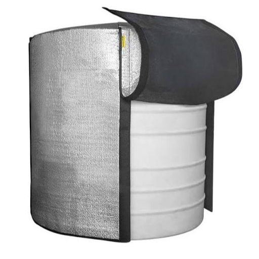
Published thermal energy storage tank insulation benchmarks, from buffer tank heat loss to district-scale stores, let you sanity-check a specification before the tank is built.
| Case | Insulation | Design ΔT | Reported loss |
|---|---|---|---|
| 300 L buffer tank | 50 mm PU | 40 K | 1.65 kWh/day (~69 W) |
| 700 gal ASME tank | R-12.5 (~2 in. foam) | 70 °F (39 K) | 869 Btu/h; 20,860 Btu/day (~6.1 kWh/day) |
| Same 700 gal tank | R-18 | 70 °F (39 K) | 604 Btu/h; 14,500 Btu/day (~4.25 kWh/day) |
| Berlin district-heating store | 400 mm glass wool (2 × 200 mm) | ~60 K | <12 W/m² |
| Generic TES screening range | n/a | n/a | 0.03–0.08%/h |
The Vattenfall store in Berlin shows the target at scale: 45 m tall, 43 m in diameter, 56 million litres at 98 °C, with 400 mm of glass wool in two 200 mm layers at 22 kg/m³. The design target is below 12 W/m². Insulation was specified around a heat-loss target, not a thickness copied from another project.
Now the arithmetic on a mid-size tank. Take a 50 m³ vertical store with H/D = 2, 200 mm mineral wool (λ = 0.040 W/m·K), an average stored temperature of 80 °C, and a 10 °C ambient:
- Geometry: D ≈ 3.17 m, H ≈ 6.34 m; total surface area ≈ 79 m².
- Resistance: R = 0.200 ÷ 0.040 = 5.0 m²·K/W; with surface resistances, U ≈ 0.19 W/m²·K.
- Bridge allowance: U × A × 1.15 ≈ 17.5 W/K.
- Loss: Q = 17.5 × 70 ≈ 1.2 kW, or 29 kWh/day.
- Share: 50 m³ across a 30 K usable swing stores 1,744 kWh; loss ≈ 1.7%/day, or 0.07%/h.
Those assumptions matter: steady temperature and ambient, no solar gain or recirculation. Real installations usually lose more. At this scale, 200 mm sits inside good practice, 150 mm above the screening range, and 300 mm below it.
The 700-gallon comparison makes the US context concrete. The federal floor is R-12.5; R-18 cuts standby loss by about 30%, from roughly 6.1 to 4.25 kWh/day (10 CFR 431.110). Germany’s AGFW FW 313 defines the annual-average method, and CHP stores below 15 W/m² can qualify for KWKG support. Different units, same question: how much heat escapes per square metre?
Thermal Storage Tank Insulation Materials Compared
Materials differ in conductivity, temperature limit, moisture behavior, and installed cost. Choose the class before the thickness.
| Material | Typical λ (W/m·K) | Typical thickness | Temperature range | Moisture behavior | Best for / watch-outs |
|---|---|---|---|---|---|
| Mineral, stone, or glass wool | 0.033–0.045 | 80–500 mm; multi-layer above ~100 mm | Up to ~650 °C | Air- and moisture-permeable; needs a vapor retarder and weatherproof jacketing | Default for medium/large hot tanks; non-combustible; watch settling and top-dome gaps |
| PUF / PIR | 0.022–0.028 | 40–120 mm | Typically ≤120 °C; PIR higher | Closed-cell; low vapor transmission, but joints and facings must be sealed | Compact commercial and chilled duty; watch temperature limits, fire behavior, UV |
| Cellular glass | 0.038–0.050 | 40–150 mm | −200 to +430 °C | Closed-cell, vapor-tight, non-combustible | Chilled, CUI-critical, and cyclic duty; higher cost and brittle |
| Flexible elastomeric | 0.032–0.040 | 25–50 mm per layer | −40 to +105 °C | Closed-cell; integral vapor resistance | Small vessels and chilled lines; limited thickness per layer |
| Vacuum insulation panels | 0.004–0.008 | 20–40 mm | ~80 °C standard skins; high-temp versions ~100–130 °C | Must remain sealed; can’t be cut or punctured | Space-constrained retrofits; λ can double over 25 years; gaps erode performance |
In practice, mineral wool tank insulation dominates hot duty, while cellular glass tank insulation dominates chilled and CUI-critical duty. Hot water storage tank insulation is a heat-loss problem. For the hot-water side, our stratified hot water storage tank guide covers zone design and heat-source selection.
Chilled duty is a moisture-control problem first. On a chilled tank, the insulation’s outer surface must stay above the dew point; otherwise it sweats, wets, and performance collapses.
Chilled service therefore favors closed-cell materials and a continuous warm-side vapor barrier. Our chilled water storage tank guide covers cooling-duty design.
Don’t pick a thickness before the system. A material that is perfect at 80 °C may be wrong at 180 °C.
How to Choose Thermal Storage Tank Insulation Thickness
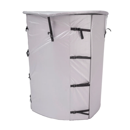
No single thickness is correct. The right number depends on duty, climate, energy price, operating hours, and material cost. The insulation thickness calculation below works for both hot and chilled duty; only the moisture control changes.
- Set the design ΔT. Mean storage temperature minus design ambient or ground temperature.
- Choose the loss target. Express it in W/m², %/day, or maximum surface temperature. District heating and CHP practice often targets below 12–15 W/m².
- Select the material class and λ at mean insulation temperature.
- Calculate the required R and thickness. R = thickness ÷ λ; U = 1 ÷ (R + R_surface).
- Apply a bridge allowance. Use 1.1 indoors and 1.15 outdoors per EN ISO 12241.
- Run the economics. Compare incremental insulation cost with capitalized heat-loss cost. Look for a 2–5 year simple payback.
- Check surface temperature and dew point, then detail supports, nozzles, manways, and penetrations before releasing the specification.
Thickness bands are a starting point, not a substitute for the calculation:
- Small commercial buffer or DHW store (0.2–2 m³): 40–100 mm PUR/PIR or 80–150 mm mineral wool.
- Medium commercial or industrial store (2–50 m³): 100–200 mm mineral wool or 60–120 mm PUF/PIR.
- Large district-heating or CHP store (100–10,000 m³): 300–500 mm, often 400 mm in two to five layers at 22 kg/m³ or more.
- Chilled-water store: 40–100 mm closed-cell insulation, set by dew point and surface temperature.
Thickness has diminishing returns. In one controlled test, a small tank at 60 °C lost 17.59 MJ over 24 hours with 10 mm of insulation, 7.32 MJ at 30 mm, 5.41 MJ at 50 mm, 4.09 MJ at 80 mm, and 2.81 MJ at 180 mm. About 90% of the reduction available at 180 mm had arrived by 80 mm; beyond that, each increment buys less and costs more.
Use the economics, not instinct. If payback exceeds your hurdle, add insulation where heat flux is highest (top, supports, uninsulated fittings) rather than thickening the whole shell. The full lifecycle model belongs in a dedicated cost and TCO study. Send your duty, energy price, and design ambient, and our engineers will run the comparison.
Insulation System Details: Vapor Barriers, Thermal Bridges and CUI
On a hot tank, the enemy is moisture ingress and thermal bridging. Specify continuous jacketing with sealed laps, insulated nozzles and manways, insulated support rings, and a bottom as carefully insulated as the sidewall. Water enters through failed seals and damaged cladding, not through the insulation itself.
On a chilled tank, the enemy is condensation. Keep the insulation surface above dew point; use closed-cell material and a continuous vapor barrier on the warm side, sealed at every joint, penetration, and support.
Thermal bridges aren’t a rounding error. Supports and pipe manifolds can account for up to 15% of standby decay. A 2 mm air gap can raise total heat loss by more than 50%.
Poorly insulated connectors have raised losses by 92–148%. A perfect sidewall can’t rescue a bare support or an unsealed penetration.
Bottom and top matter too. Bottom insulation cut losses by 24% in one experimental setup, and blocking natural circulation during standby cut them by 48%. In that work, measured UA fell from 12.2 to 6.5 W/K, still about 3.8 times the theoretical minimum. Real tanks underperform theory because legs, flanges, expansion tanks, and thermosiphoning are part of the system.
Corrosion under insulation is the long-term failure mode. Wet mineral wool can raise effective conductivity and increase standby losses by 150–300% while corroding the shell. Specify sealed cladding, drainage paths, a coated shell, removable covers at inspection points, and an inspection plan aligned with API RP 583. Our guide to corrosion protection for steel tanks covers the coating side.
Installation, Inspection and Maintenance
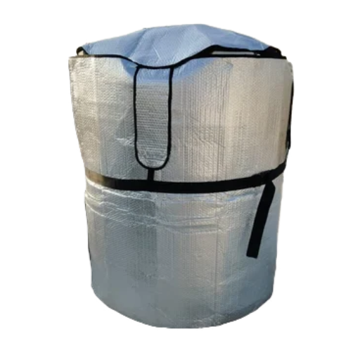
Insulation quality is an installation outcome, not a catalogue property. One solar installation measured an effective R of 1.8–2.3 against a theoretical 12.8, because legs, flanges, expansion tanks, and thermosiphoning are part of the system.
Commissioning should verify thickness and continuity, seal every lap, inspect penetrations, confirm surface temperatures, and record a baseline. A temperature-decay test or measured UA gives you a number to compare later.
Inspect jacketing and seals visually, use infrared thermography for wet insulation, and apply pulsed eddy current or targeted insulation removal where CUI is suspected. Check after every maintenance event that opens the cladding. Repair small breaches immediately. Water is the dominant degradation path.
Practitioners learn this the practical way. One owner of a 1,040-gallon tank put 4–5 inches of closed-cell foam on the bottom, roughly R-18 to R-20, planned about 6 inches on top, and reported the foam was cool to the touch at 187 °F. The lesson: the bottom and top got the same attention as the sidewall.
FAQ
What is standby heat loss in a thermal storage tank?
Standby heat loss, also called standing heat loss, is the energy a tank sheds while idle: no charging, no draw. It flows through the shell, top, bottom, supports, nozzles, and manway, and is expressed in watts, kWh/day, W/m², or as a percentage of stored energy per hour.
How do you calculate standby heat loss?
Use Q = U × A × ΔT: overall heat-transfer coefficient × external surface area × tank-to-ambient temperature difference. Multiply by 24 for daily energy, then divide by stored energy for the percentage lost per day.
How much heat does a thermal store lose per day?
A well-insulated commercial or district-heating store typically loses about 0.03–0.08% of stored energy per hour, or roughly 0.7–1.9% per day. Smaller tanks and poorly detailed systems run higher. Treat the range as a screening check, not a guarantee.
What insulation thickness does a thermal storage tank need?
There’s no universal number. Small commercial tanks use 40–100 mm of PUR/PIR or 80–150 mm of mineral wool; medium industrial tanks use 100–200 mm; large district-heating stores use 300–500 mm. The right thickness is the economic optimum for your energy price, climate, and operating hours.
What is the best insulation for a thermal storage tank?
For hot duty, mineral wool is the default: non-combustible, widely available, and rated to about 650 °C. For chilled or cyclic duty, cellular glass or closed-cell foam is usually better because moisture control matters more than raw conductivity. The right choice depends on temperature, moisture exposure, and fire requirements.
Does a thermal store need insulation underneath?
Yes. In one experimental setup, bottom insulation cut losses by 24%. Insulate the base, top, supports, nozzles, and manways, not just the visible sidewall. The bottom also needs a load-bearing detail that carries the tank’s weight.
Why do chilled water tanks need a vapor barrier?
On a chilled tank, the insulation’s outer surface can fall below the surrounding air’s dew point. Without a continuous warm-side vapor barrier, moisture enters the insulation, condenses, and destroys performance while promoting corrosion. Closed-cell insulation and sealed joints are the standard defense.
Conclusion
Standby heat loss is set by four things: U, surface area, ΔT, and time. Thermal storage tank insulation changes U; geometry changes A; the duty changes ΔT; and the operating profile changes idle time. Supports, nozzles, manways, top and bottom insulation, vapor barriers, and jacketing decide whether the installed system delivers the calculated performance.
Five actions for your next project:
- Set a heat-loss target in W/m² or %/day before comparing quotes.
- Choose the material class for hot or chilled duty, then calculate thickness.
- Apply a bridge allowance and detail every penetration.
- Specify a vapor barrier and a CUI inspection plan.
- Check the installed system at commissioning, not just the datasheet.
If you’re planning a thermal storage tank, send us your duty, design temperatures, and ambient conditions. We’ll help you specify a thermal storage tank insulation system that meets your heat-loss target (hot or chilled, indoor or outdoor) and fabricate the vessel around it. Talk to our engineers to request a quote.