Every gas station on Earth operates inside a classified hazardous area. Most owners never realize how extensive those zones are until an inspector flags uncertified equipment, an insurer voids coverage, or worse — a spark ignites vapor that should have been contained. Hazardous area classification is not an academic exercise. It is the foundation of every safety decision at a fueling facility.
If you are building a new station, expanding an existing forecourt, or auditing compliance, understanding how to map Zone 0, Zone 1, and Zone 2 boundaries is essential. This guide walks you through the entire process: what hazardous area classification means, how the three zones apply to fuel retail, how global standards differ, and how to conduct a classification study that keeps your operation safe and compliant.
In the sections ahead, you will learn:
- The definitions and time-based benchmarks for each hazard zone
- How the IEC Zone system maps to the North American Class and Division framework
- Practical zone boundaries for typical gas station layouts
- The step-by-step process for conducting a formal Hazardous Area Classification study
- Common mistakes that trigger failed inspections and costly shutdowns
- What misclassification actually costs in real money
For detailed information about Explosion-Proof Gas Station Equipment, please refer to our article about Explosion-Proof Gas Station Equipment.
What Is Hazardous Area Classification?

Definition and Purpose
Featured Snippet Target: Hazardous area classification is the systematic process of dividing locations where explosive atmospheres may occur into zones based on the frequency and duration of their presence. It determines what certified equipment can be installed, where it can be placed, and how a facility must be maintained to prevent ignition of flammable gases or vapors.
At its core, hazardous area classification answers one question: How likely is an explosive gas-air mixture to exist at this exact location? The answer drives every subsequent engineering and purchasing decision. Without it, buyers cannot specify the right equipment protection level, insurers cannot assess risk accurately, and regulators cannot verify compliance.
Why It Matters for Fuel Retail
Gasoline and diesel vapors are heavier than air. They pool in low points, drift across forecourts, and accumulate inside enclosures. A single uncertified electrical device in the wrong zone creates an ignition risk that endangers customers, staff, and the surrounding community. Classification is what transforms vague safety concerns into precise, actionable boundaries that engineers, installers, and inspectors can all verify.
In 2023, a station operator in Southeast Asia assumed the entire forecourt was Zone 2. Standard CCTV housings were installed around the dispenser islands to cut costs. During a routine fuel delivery, a vapor leak triggered the gas detection alarm. The fire authority ordered an immediate Hazardous Area Classification review and found that the dispenser nozzle vicinity should have been Zone 1. The station was shut for three days, costing 8,000 in lost revenue plus 5,000 in emergency reclassification consulting. The savings from uncertified cameras were erased in hours.
The Three Zones at Gas Stations
Zone 0: Continuous Hazard
Zone 0 covers areas where an explosive gas atmosphere is present continuously or for long periods. At a gas station, this means inside underground fuel storage tanks, in the vapor space above liquid fuel, inside sealed process vessels, and within tanker compartments during loading. The wet portion of tank sumps and closed vapor recovery piping also typically qualify as Zone 0.
Equipment installed in Zone 0 must carry Category 1G certification and Equipment Protection Level Ga. Only intrinsic safety (Ex ia) or specially encapsulated equipment is generally acceptable here. For most station operators, Zone 0 is not a place where you install active electrical equipment. It is a boundary condition that defines what happens at the edges — tank vents, fill points, and vapor recovery connections.
Zone 1: Likely During Normal Operation
Zone 1 covers areas where an explosive atmosphere is likely to occur periodically during normal operation. This is the zone that catches most station owners by surprise because it extends well beyond the obvious leak points.
At a fueling facility, Zone 1 typically includes:
- The immediate vicinity around fuel dispenser nozzles and hoses
- Tank fill points and vent pipe outlets
- Pump seals and compressor connections
- Sampling points and drain connections
- The area directly beneath dispenser islands and sumps
Equipment for Zone 1 requires Category 2G and EPL Gb. Flameproof enclosures (Ex d), increased safety designs (Ex e), and pressurized systems (Ex p) are commonly used in these locations. Most retail fuel dispensers are engineered with Zone 1 ratings because the nozzle area is inherently a release source during every refueling event.
Zone 2: Unlikely or Short Duration
Zone 2 applies where an explosive atmosphere is not likely to occur during normal operation, and if it does occur, it persists only for a short time. General forecourt areas, well-ventilated canopy perimeters, and perimeter patrol routes typically fall under Zone 2.
This does not mean Zone 2 is safe for standard consumer electronics. It means the risk is lower, and the equipment requirements are correspondingly less stringent. Category 3G and EPL Gc equipment, including non-sparking (Ex n) devices, is acceptable in Zone 2. However, many operators choose Zone 1-rated equipment for Zone 2 locations to provide additional safety margins and simplify spare parts inventory.
Zone vs. Time Benchmarks
| Zone | Definition | Approximate Duration | Risk Level | Typical Gas Station Location |
|---|---|---|---|---|
| Zone 0 | Continuous or long-period presence | >1,000 hours/year | Highest | Inside storage tanks, vapor space, sealed piping |
| Zone 1 | Likely during normal operation | 10-1,000 hours/year | High | Dispenser nozzles, tank vents, fill points, pump seals |
| Zone 2 | Unlikely; short duration only | <10 hours/year | Moderate | General forecourt, canopy perimeter, well-ventilated areas |
Zone System vs. Class and Division System

IEC/ATEX Zone System
The globally recognized Zone system is defined by IEC 60079-10-1 and adopted under the European ATEX Directive 2014/34/EU. It classifies areas based on the probability and duration of explosive atmosphere presence using the Zone 0, Zone 1, and Zone 2 framework described above. This system is used across Europe, Asia-Pacific, the Middle East, Africa, and anywhere IECEx certification is accepted.
North American Class and Division Framework
In the United States and Canada, the National Electrical Code (NEC Articles 500-505) and NFPA 30A use a Class and Division system that maps functionally to the Zone approach but uses different terminology.
Class I, Division 1 covers locations where flammable gases or vapors exist under normal operating conditions. It corresponds approximately to Zone 0 and Zone 1 combined. Fuel dispenser islands, tank vents, and fill points in North America are typically treated as Class I, Division 1.
Class I, Division 2 covers locations where flammable vapors exist only under abnormal conditions, such as equipment failure or accidental release. It aligns roughly with Zone 2. General canopy and forecourt areas often qualify as Division 2.
NFPA 30A, the Code for Motor Fuel Dispensing Facilities, provides specific guidance on electrical installations at gas stations in North America. It references these classifications to determine wiring methods, equipment ratings, and installation clearances.
Direct Comparison Table
| Characteristic | Zone System (IEC/ATEX) | Class/Division System (NEC) |
|---|---|---|
| Continuous hazard | Zone 0 | Class I, Division 1 |
| Likely in normal operation | Zone 1 | Class I, Division 1 |
| Unlikely; abnormal only | Zone 2 | Class I, Division 2 |
| Primary standard | IEC 60079-10-1 | NEC Articles 500-505 |
| Fuel retail guidance | EN 13617, CECOD Guide | NFPA 30A, NEC Article 514 |
| Equipment marking | Ex db IIB T6 Gb | Class I, Div 1, Group D, T6 |
Typical Gas Station Zone Layout
Underground Tank Area
The interior of underground storage tanks is Zone 0. The area immediately surrounding tank fill ports, gauge openings, and vent pipes is typically Zone 1. Depending on ventilation and the height of the vent outlet, a radius of 1 to 3 meters around the vent may qualify as Zone 1. The general tank pad area, if well ventilated, is usually Zone 2.
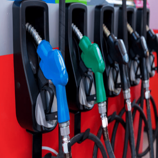
Dispenser Island and Nozzle Vicinity
The dispenser island is the most visible Zone 1 area at a gas station. The immediate vicinity around nozzles, hoses, and breakaways is classified Zone 1 because vapor is released during normal refueling operations. The horizontal extent of this zone depends on local standards but commonly extends 0.5 to 1.5 meters from the nozzle in all directions. The area beneath the dispenser, including the sump, may be Zone 1 or Zone 0 depending on liquid accumulation and vapor recovery design.
Tank Fill Point and Vent Pipes
Tank fill connections are active release sources during every delivery. The area around the fill cap and any vapor recovery connections is Zone 1. Vent pipes release vapor to the atmosphere, and the zone around the vent outlet depends on discharge height, prevailing wind, and nearby structures. A vent terminating less than 3 meters above ground may create a larger Zone 1 or Zone 2 area than a vent extending to 4 meters or more.
General Forecourt and Canopy
The open, well-ventilated areas of the forecourt surrounding the dispenser islands are typically Zone 2. These are locations where explosive atmospheres are unlikely during normal operation and would only appear briefly under abnormal conditions, such as a major spill or equipment failure. Poor ventilation, enclosed canopies with limited airflow, or low-lying areas where vapor can accumulate may expand Zone 2 boundaries or even create localized Zone 1 conditions.
Vapor Recovery Systems
Stage II vapor recovery systems, where still required, create additional release points at nozzle boots, hose connections, and recovery unit enclosures. Each connection point must be evaluated as a potential release source. In many jurisdictions, vapor recovery piping is treated similarly to fuel piping for classification purposes, with enclosed or low points classified more restrictively than open, ventilated sections.
Gas Groups and Temperature Classes
Gas Groups for Fuel Applications
Equipment Protection Level is only part of the equation. The gas group indicates which flammable gases the equipment can safely handle without igniting them.
Group IIA covers the least hazardous gases, including propane and most hydrocarbons with high ignition energy requirements. Group IIB covers gases such as ethylene and the vapors from gasoline and diesel, which represent the typical hazard at fuel retail facilities. Group IIC is the most stringent classification, covering hydrogen and acetylene, and equipment rated IIC is automatically suitable for IIA and IIB applications.
Gasoline vapors typically fall under Group IIB. However, stations planning to add hydrogen refueling, compressed natural gas, or other alternative fuels must evaluate whether Group IIC-rated equipment is required. The broader explosive range of hydrogen can turn an IIB-rated Zone 1 area into a more restrictive condition.
Temperature Classes T1 Through T6
The temperature class indicates the maximum surface temperature that equipment can reach during operation. The classification runs from T1 (maximum 450°C) down to T6 (maximum 85°C). Gasoline auto-ignites at approximately 280°C, so T6-rated equipment with an 85°C maximum surface temperature provides the widest safety margin. For fuel dispensing environments, T6 is the preferred standard. It ensures that even under fault conditions, equipment surfaces remain far below the ignition point of surrounding vapors.
Global Standards and Regulations

IEC 60079-10-1 (International)
IEC 60079-10-1 is the international standard for the classification of areas where explosive gas atmospheres may be present. It provides the methodology for identifying release sources, assessing release rates, evaluating ventilation, and defining zone extents. The standard is methodical and quantitative where possible, making it the reference framework for most HAC studies outside North America.
ATEX Directive 2014/34/EU (Europe)
The ATEX Directive governs both equipment and workplace safety in potentially explosive atmospheres within the European Union. Equipment must carry CE marking with the Ex symbol, category numbers, and Equipment Protection Levels. For petrol stations, the CECOD Guide provides practical guidance on applying ATEX principles to fuel retail sites, while EN 13617 specifically addresses fuel dispensers at filling stations.
API RP 505 (US Petroleum Industry)
API RP 505 is the American Petroleum Institute’s Recommended Practice for classification of locations for electrical installations at petroleum facilities using the Zone system. It aligns closely with IEC 60079-10-1 but includes petroleum-industry-specific guidance on release source identification and zone boundary distances.
NFPA 30A and NEC Article 514 (US Fuel Retail)
NFPA 30A, the Code for Motor Fuel Dispensing Facilities, incorporates NEC Article 514 for classification of hazardous locations around dispensers, tanks, and vents. While historically using the Class and Division system, the NEC also permits Zone classification under Article 505. Fuel station designers in the United States must verify which system their local authority has jurisdiction over.
If you need to understand NFPA 30A Compliance, please read our article about NFPA 30A Compliance.
GB/T 3836 (China)
China maintains its own explosion-proof standards through the GB/T 3836 series, which aligns with IEC 60079 but includes domestic adaptations. CNEx and NEPSI are the primary certification bodies. For Chinese manufacturers exporting equipment, understanding both GB/T 3836 and target market standards is essential.
If you are not sure which certification you need, you can check out our article on ATEX vs IECEx vs UL.
How to Conduct a Hazardous Area Classification Study
Conducting a formal HAC study requires methodical documentation. Follow these six steps to produce a classification that regulators, insurers, and equipment suppliers can all work from.
Step 1: Identify Release Sources
Walk the entire facility and list every point where flammable gas or vapor could be released into the atmosphere. At a gas station, this includes tank fill ports, vents, dispenser nozzles, hose connections, pump seals, sampling points, drain valves, and vapor recovery connections.
Step 2: Assess Release Frequency and Duration
For each source, determine how often releases occur and how long they persist. A tank vent that releases with every delivery is a different risk profile than an emergency overflow drain that opens only during catastrophic failure. Use the zone definitions to classify each source location.
Step 3: Evaluate Ventilation
Ventilation is the single most important factor in determining zone extent. Open-air forecourts with natural airflow may limit Zone 1 to a small radius around release sources. Enclosed areas, underground sumps, and buildings with limited airflow can expand zones dramatically or raise classifications from Zone 2 to Zone 1.
Step 4: Define Zone Boundaries
Using standard guidance from IEC 60079-10-1, API RP 505, or NFPA 30A, draw horizontal and vertical boundaries for each zone. Document the rationale for each boundary distance. Typical horizontal extents range from 0.5 to 3 meters for Zone 1 around dispensers and vents, but site-specific conditions always take precedence.
Step 5: Document on Drawings
Produce scaled hazardous area classification drawings showing Zone 0, Zone 1, and Zone 2 boundaries on a site plan. Include elevation views where vertical boundaries matter, such as around elevated vent outlets or beneath canopy structures. These drawings become the legal reference for equipment installation and future modifications.
Step 6: Review Against Equipment Ratings
Compare every piece of planned electrical and mechanical equipment against the zone classification where it will be installed. Verify gas group compatibility, temperature class, protection method, and certification body recognition. Any mismatch must be resolved before installation begins.
Need to know the difference between Intrinsic Safety and Explosion-Proof? Please read our article about Intrinsic Safety vs Explosion-Proof.
Common Classification Mistakes
Even experienced engineers make errors during hazardous area classification. These five mistakes appear repeatedly in failed inspections and incident investigations.
Underestimating Zone 0 extents. The interior of tanks, sumps, and closed piping is often treated as “just a tank” rather than Zone 0. Any equipment installed inside or opening into these spaces must carry the highest protection ratings.
Ignoring ventilation effects. A well-ventilated open forecourt may keep Zone 1 areas small. But add a solid wall, lower the canopy, or enclose the dispenser area, and the same release sources can create larger or more restrictive zones.
Using Zone 2 equipment in Zone 1. This is the most common violation found during inspections. A standard industrial junction box or camera housing may look rugged, but if it lacks Zone 1 certification, it is non-compliant and dangerous.
Failing to update after modifications. Every station change — new dispenser islands, relocated vents, added canopy structures, or modified vapor recovery — requires a classification review. The original drawings become outdated the moment the physical layout changes.
Missing hydrogen refueling implications. Hydrogen’s explosive range is far broader than gasoline vapor, and its ignition energy is lower. Stations adding hydrogen must re-evaluate gas groups, zone extents, and equipment ratings from the ground up.
Cost of Misclassification
Misclassification is expensive in multiple ways. The most visible cost is equipment replacement. When an inspector finds Zone 2 equipment installed in a Zone 1 location, every non-compliant device must be removed and replaced before the station can operate legally.
In 2022, a fuel retailer in West Africa expanded from two to four dispenser islands without updating their HAC drawings. The new fill point was positioned closer to an electrical control panel than the original design allowed. During a routine regulatory audit, the entire expanded section was found to violate Zone 1 boundaries. Four dispensers, two CCTV housings, and one payment terminal had to be replaced with certified alternatives. The direct equipment cost was 12,000. The three-week shutdown during replacement costs an additional 18,000 in lost revenue.
Beyond direct replacement costs, misclassification creates insurance and liability exposure. Insurers increasingly require documented HAC drawings as a condition of coverage. After an incident, investigators will compare the installed equipment against the classification. Mismatched ratings can shift liability from equipment failure to installation negligence.
2025-2026 Regulatory Updates

The regulatory landscape for hazardous area classification continues to evolve. Several updates in 2025 and 2026 affect how fuel stations are classified and what equipment standards apply.
The global hazardous area equipment market, valued at approximately 7.95 billion to 15.58 billion in 2025, depending on scope, is growing at 5.8% to 7.9% CAGR according to market research from Future Market Insights and Mordor Intelligence. This growth is driving tighter enforcement and faster adoption of updated standards.
In the United States, NFPA 30A continues to integrate with evolving NEC provisions for motor fuel dispensing facilities. The 2024 edition includes refined guidance on classified locations for alternative fuel dispensers, including hydrogen and compressed natural gas.
IEC 60079-10-1 remains under periodic revision, with the latest editions providing more detailed quantitative methods for estimating zone extents based on release rate and ventilation calculations. These methods allow more precise classification than the conservative rule-of-thumb distances used historically.
Hydrogen infrastructure standards are expanding rapidly. NFPA 2 and ISO 19880 now establish specific requirements for hydrogen dispensing areas, including reclassified zone extents and Group IIC equipment mandates. Stations planning dual-fuel capability must account for these overlays in their HAC studies.
In China, GB 46031-2025 introduced stricter explosion-proof technical specifications effective February 1, 2026, while GB 12710-2024 updated coking safety regulations in July 2025. Chinese manufacturers exporting hazardous area equipment must ensure compliance with both domestic and target market standards.
Frequently Asked Questions
What is hazardous area classification?
Hazardous area classification is the systematic process of dividing locations where explosive atmospheres may occur into zones based on the frequency and duration of their presence. It determines what certified equipment can be installed and how a facility must be maintained to prevent ignition.
What are Zone 0, Zone 1, and Zone 2 at a gas station?
Zone 0 covers areas with continuous explosive atmosphere presence, such as inside storage tanks. Zone 1 covers areas where explosive atmospheres are likely during normal operation, such as around dispenser nozzles and tank vents. Zone 2 covers areas where explosive atmospheres are unlikely and short-lived if they occur, such as general forecourt areas.
How does the Class and Division system compare to Zones?
Class I, Division 1 corresponds approximately to Zone 0 and Zone 1 combined. Class I, Division 2 corresponds roughly to Zone 2. The Zone system is used internationally under IEC and ATEX, while Class and Division are used in North America under the NEC.
What standard governs hazardous area classification for gas stations?
Internationally, IEC 60079-10-1 provides the methodology. In Europe, the ATEX Directive 2014/34/EU applies. In the United States, NFPA 30A references NEC Articles 500-505. API RP 505 provides petroleum industry guidance. For European petrol stations, EN 13617 and the CECOD Guide offer specific fuel retail guidance.
How far does Zone 1 extend around a fuel dispenser?
The exact distance depends on local standards, ventilation, and site-specific conditions. Typical horizontal extents range from 0.5 to 1.5 meters from the nozzle in all directions. Vertical extents beneath the dispenser island may also apply.
Conclusion
Hazardous area classification is the invisible framework that makes safe fuel retail possible. Every zone boundary on a classification drawing represents a decision about risk, engineering, and legal compliance. Get it right, and your station operates with confidence. Get it wrong, and the costs cascade through inspections, insurance, equipment replacement, and worst of all, safety incidents.
Here are the five key takeaways to remember:
- Classify first: Map Zone 0, Zone 1, and Zone 2 before selecting or installing any electrical equipment.
- Follow the standards: Use IEC 60079-10-1, ATEX, NFPA 30A, or the framework recognized in your jurisdiction.
- Document everything: Maintain scaled HAC drawings and update them whenever the station layout changes.
- Match equipment exactly: Gas group, temperature class, protection method, and zone rating must all align.
- Plan for alternatives: Hydrogen, CNG, and other fuels may require reclassification from the ground up.
If you are planning a new station, expanding an existing facility, or need a formal Hazardous Area Classification study, contact Shandong Shengrui Intelligent Equipment Co., Ltd. Our engineering team designs, certifies, and exports complete gas station systems tailored to your zone requirements and market standards. We provide the classification guidance and the certified equipment to match it.