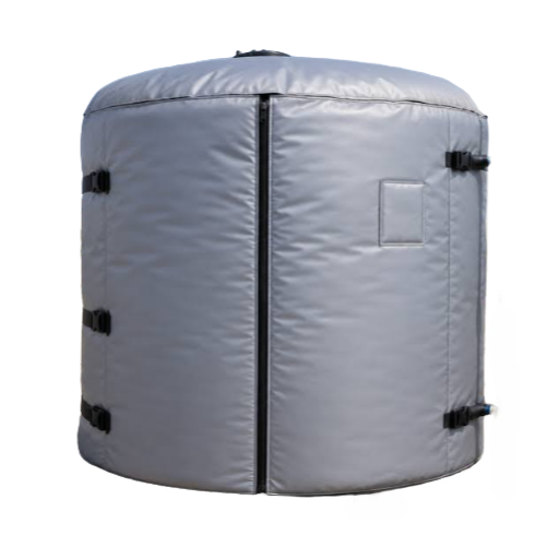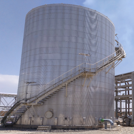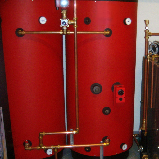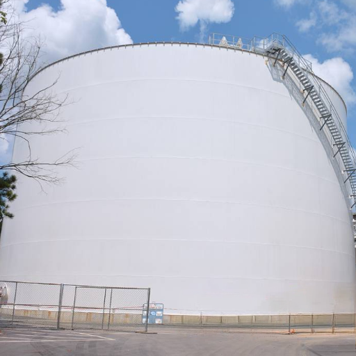
A building needs 100 kWh of usable heat between 45 °C and 60 °C. A water tank working across that 15 K band needs about 5.7 m³. A well-specified phase change material thermal storage tank might need 2.5 m³. That’s roughly half the volume, and nothing like the “five times smaller” claim on some datasheets.
Material-level density is real, but encapsulation, heat exchangers, void space, and insulation consume much of it. A PCM thermal storage tank is not a bag of salt in a steel shell. It’s a heat-exchanger project with a chemistry attached.
Buyers get into trouble when they buy the chemistry and inherit the engineering. A unit can meet its datasheet and still raise costs, because its melting point forces a heat pump to run hotter. Another can pass a leak test and deliver half its rating, because the PCM never fully melts.
This guide covers how PCM storage works, when it beats water, architectures, sizing, failure modes, standards, cost, and installation. Start with our thermal store tank guide for the wider picture.
What Is a Phase Change Material Thermal Storage Tank?
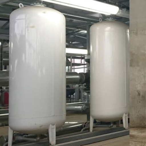
A PCM thermal storage tank, sometimes marketed as a PCM heat battery, is an insulated vessel that stores heat or cooling in a phase change material. This is latent heat thermal energy storage: the material absorbs heat as it melts and releases it as it freezes, so the tank holds more energy in a smaller volume and delivers it at a nearly constant temperature.
Three parts matter. The PCM is the medium: a salt hydrate, paraffin, fatty acid, bio-based material, or ice. The containment keeps it separate from the heat-transfer fluid. The heat exchanger and controls move energy and track the state of charge.
Keep the boundaries straight. The shell is the pressure boundary, the capsules are the storage matrix, the exchanger is the power path, and the controls decide how much stored energy you can use. A PCM tank shifts energy in time; it doesn’t generate it.
How Phase Change Material Thermal Storage Tanks Work: Charging and Discharging
During charging, warm heat-transfer fluid, usually water or a water-glycol mix, passes through or around the PCM. The PCM melts at its phase-change temperature and absorbs a large amount of energy without a large temperature rise. During discharging, cooler fluid returns, the PCM freezes, and latent heat moves back into the fluid.
Most energy is exchanged at a nearly constant temperature, unlike water, which delivers heat over a falling range. The PCM and surrounding water also store sensible heat, but the latent plateau does most of the work.
Heat transfer is the bottleneck. As PCM freezes onto a cold surface, it forms an insulating solid layer. The melting front moves through the tank, so power varies through the cycle.
Melting is often assisted by natural convection; freezing is conduction-limited and slower. A tank that charges in three hours may need five to discharge. Ask for both curves.
Once fully melted, the PCM is a warm block of wax or salt with no latent capacity. That’s why usable-capacity factors exist.
PCM vs Water Thermal Storage: When Latent Heat Wins
Water wins on cost, simplicity, and heat transfer. It’s the default unless space or temperature stability is the constraint. A phase change material thermal storage tank wins on volume, stable discharge temperature, and retention in a narrow band.
Compare density at the same boundary. Salt hydrates reach 69–143 kWh/m³ at material level and paraffins 18–89; water holds about 23 kWh/m³ at ΔT 20 K and 69 at 60 K. A commercial PCM unit usually lands at 27–46 kWh/m³ after encapsulation and heat exchangers. So PCM is often one and a half to two times denser than water at a narrow ΔT, not five times at system level.
| Factor | Water (sensible) | PCM (latent) |
|---|---|---|
| Material-level density | ~23 kWh/m³ at ΔT 20 K; ~69 at ΔT 60 K | Salt hydrates ~69–143 kWh/m³; paraffins ~18–89 |
| System-level density | ~20–70 kWh/m³ depending on ΔT | Commercial units ~27–46 kWh/m³ |
| Discharge temperature | Falls as the tank cools | Nearly constant near the melting point |
| Installed cost (directional) | ~$54–97/kWh before auxiliaries | ~155/kWh; 155/kWh; 69/kWh with graphite enhancement |
A hybrid can be the pragmatic answer. Adding capsules to a water tank raises capacity without a full redesign. A Swiss pilot with a 762 L tank, 280 L of water, and 3,500 salt-hydrate capsules at about 45 °C measured usable capacity up to 80% higher than water alone. If you are 20–30% short on space, ask about a hybrid.
Phase Change Material Thermal Storage Tank Designs and Encapsulation
Architecture and PCM encapsulation decide whether the chemistry can perform. The most common commercial form is a packed bed of capsules in a water tank, where water acts as both heat-transfer fluid and sensible storage. It’s modular and familiar, but pressure drop, capsule settling, void fraction, and incomplete melting matter.
Macro panels are easier to replace, but offer less surface area. Shell-and-tube designs put PCM on the shell side and fluid through finned tubes; they suit pressurized, higher-power duty, but tube spacing and fin design decide the result. PCM slurry offers high surface area for compact cooling at the cost of viscosity and pumping power. Cascade tanks stack several melting points for a wide duty, with more complexity and cost.
| Architecture | Heat transfer | Complexity | Best fit | Watch-outs |
|---|---|---|---|---|
| Packed-bed capsules | Moderate | Moderate | Retrofits, hybrid water+PCM, DHW | Pressure drop, settling, void fraction, breakage |
| Macro panels/modules | Lower | Low–moderate | Retrofits, small commercial | Slower power, replacement access, thermal bridging |
| Shell-and-tube | Good, designable | Moderate–high | Pressurized and industrial duty | Tube spacing, fin design, PCM shrinkage |
| PCM slurry | High surface area | High | Data centers, transport, compact cooling | Viscosity, stability, pumping power, cost |
| Cascade / multi-PCM | Good exergy match | High | DHW plus space heating, district energy | Cost, controls, interface design |
Choose the architecture after defining the duty and allowable pressure drop. Floating capsules and settling beds are common in pilot builds. For cooling, see chilled water thermal storage.
Choosing the Right PCM Material
Start with melting point, not latent heat; enthalpy at the wrong transition temperature is useless. Then compare usable latent heat, compatibility, cycling stability, and cost.
Salt hydrate PCM formulations offer high density, non-flammability, low cost, and conductivity around 0.5–1.4 W/m·K. They also supercool, segregate, and corrode. They suit DHW, district heating, solar, and cold storage when containment is proven.
Paraffin PCM formulations are stable and non-corrosive, but have low conductivity around 0.16–0.35 W/m·K, are flammable, and change volume. They suit HVAC and cold chain.
Fatty acids are renewable, with lower latent heat. Ice/water is cheapest but cooling-only. Eutectics are sharp and tunable, at a cost penalty.
| Family | Melting range | Latent heat | Pros | Cons | Best fit |
|---|---|---|---|---|---|
| Salt hydrates | ~8–88 °C; sub-zero variants | ~115–280 kJ/kg | Dense, non-flammable, good conductivity | Supercooling, segregation, corrosion | DHW, district heating, cold storage |
| Paraffins | ~−4 to 100 °C | ~85–266 kJ/kg | Stable, non-corrosive, wide range | Low conductivity, flammable, volume change | HVAC, electronics, cold chain |
| Fatty acids / bio-based | ~8–80 °C | ~150–250 kJ/kg | Renewable, stable | Lower latent heat, supply variability | Low-temperature cooling, green buildings |
| Ice/water | ~0 °C | ~333 kJ/kg | Cheapest, highest per kg | Cooling-only, bulky | Chilled-water and ice storage |
| Eutectics | Tunable, e. g., 20–70 °C | ~150–250 kJ/kg | Sharp, tunable transition | Cost, limited availability | Niche HVAC, transport |
Match the transition temperature to the application: cold chain −30 to +6 °C, HVAC 5–28 °C, domestic hot water 40–65 °C, district heating 50–85 °C, industrial waste heat 70–89 °C.
This is where the heat-pump trap appears. A PCM melting at 58 °C needs water flow around 60–70 °C to charge fully. An air-source heat pump can do that, but spends most of the charge where COP is poorest.
A cylinder charged at 45–50 °C only loses efficiency at the end. If efficiency matters more than space, choose a lower-temperature PCM.
For a detailed comparison, please read our article on thermal store vs buffer tank.
How to Size a Phase Change Material Thermal Storage Tank
PCM tank sizing is a sequence, not a volume lookup:
- Define usable load in kWh and required discharge power in kW.
- Choose a melting point inside the system’s useful temperature band.
- Estimate usable latent heat per kilogram, not the datasheet peak.
- Add sensible heat over the usable temperature swing.
- Apply a void fraction of roughly 0.2–0.4 for capsules or modules, plus a usable-capacity factor for incomplete melting and heat-exchanger approach.
- Convert mass to material volume, then to tank volume using bulk density and packing.
- Check power: the heat exchanger must deliver the kW, not just the kWh.
Worked example for a phase change material thermal storage tank: 100 kWh of useful latent storage, a salt hydrate with 200 kJ/kg latent heat and 1,500 kg/m³ bulk density, 0.65 capsule fill fraction, and 0.80 usable-capacity factor.
- Required PCM mass: 100 × 3,600 ÷ 200 = 1,800 kg
- Material volume: 1,800 ÷ 1,500 = 1.2 m³
- Tank volume: 1.2 ÷ 0.65 = 1.85 m³, before insulation and headspace
- Nameplate needed to deliver 100 kWh: 100 ÷ 0.80 = 125 kWh
Sanity-check against water. The same 100 kWh across a 30 K swing needs 100 × 3,600 ÷ (4.18 × 1,000 × 30) ≈ 2.87 m³. The PCM tank is smaller, but not five times smaller.
The assumptions, not the chemistry, decide the answer. Our thermal storage tank sizing guide covers the full sensible-water method.
The Engineering Challenges That Decide Performance
Most failures in a phase change material thermal storage tank are containment and heat-transfer failures, not chemistry failures.
Supercooling means the PCM freezes below its melting point, so heat arrives colder than designed. One calcium chloride hexahydrate study measured about 11 °C of undercooling and segregation after 40 cycles. Nucleating agents and proven capsule geometry are the usual mitigations.
Phase segregation affects incongruently melting salt hydrates: layers separate and capacity fades irreversibly. A Gothenburg district-cooling store showed both problems in 168 kg cycling tests; a 3 wt% thickener fixed it. Corrosion and leakage are containment failures, so they require a wetted-material compatibility report and a leak-tightness method.
Incomplete melting leaves dead PCM near walls or inside large capsules; one full-scale store delivered 99 of 275 rated kWh, about 36%. Fins, thin layers, and flow distribution are the fixes. Cycling degradation can take 20–30% over 1,000–2,000 cycles. Flammability matters for paraffins, and container stress follows volume change of roughly 5–19%.
| Failure mode | What happens | What to specify |
|---|---|---|
| Supercooling | Freezing occurs below the melting point; output drops | Nucleating agents, proven geometry, cycle testing |
| Phase segregation | Layers separate; capacity fades irreversibly | Thickener, third-party cycling data |
| Corrosion and leakage | Salts attack metal; PCM escapes into fluid | Compatibility report, inhibitors, leak-tightness method |
| Incomplete melting | Rated mass does not deliver rated capacity | Fins, thin layers, smaller capsules, flow distribution |
| Cycling loss | Capacity falls over years | Cycle data and a capacity-retention warranty |
| Flammability and stress | Organic PCM adds fuel load; volume change cracks containers | Flame retardants, non-combustible enclosure, ullage, relief |
Containment and heat transfer decide whether a good material becomes a good tank.
Standards, Testing, and Performance Verification
Standards turn “trust us” into a document request.
RAL-GZ 896, in its August 2025 edition, is the German quality and testing standard for phase change materials. It covers phase-transition range, stored energy, conductivity, cycling stability, and leak-tightness.
ASTM C1784 is the US heat-flow-meter method for transition temperature and enthalpy. IEA SHC Task 67 / ES Task 40 covers characterization, a material database, state of charge, and durability. In China, T/CABEE 033-2022 addresses PCM heating systems, while JG/T 534-2018 covers building products.
For any PCM thermal storage tank, ask every supplier for six things:
- Third-party cycle data, not a manufacturer datasheet.
- An enthalpy–temperature curve, not one latent-heat number.
- A corrosion compatibility report for the wetted materials.
- The leak-tightness test method and acceptance criteria.
- A factory or independent performance test at your design ΔT.
- A warranty tied to capacity retention, not just years.
A ten-year warranty that excludes capacity is a warranty on the paint.
Cost, Payback, and When PCM Beats Water
Costs for a phase change material thermal storage tank are quoted at three boundaries, and they’re not comparable. Material runs about €10–50/kWh for commodity salts or paraffins. Compact commercial systems have been listed around €200–340/kWh, with specific units around €330–340/kWh.
Installed NREL-modelled PCM was about $155/kWh for an n-tetradecane store, falling to about $69/kWh with graphite enhancement, as summarized in this water-vs-PCM analysis. A water vessel was cited at $54–97/kWh before auxiliaries. DOE’s target is $24/kWh.
Payback follows tariff and utilization, not the PCM alone. About four years is possible for a residential air-source heat pump retrofit with low-cost conductivity enhancement and a strong peak-shaving tariff. District-scale integration has reported simple paybacks around 19–25 years. Both can be true; the boundaries differ.
Choose PCM when space, temperature stability, or peak shifting is worth a capital premium. Choose water when cost, simplicity, and fast heat transfer dominate. If you’re close on space, a hybrid may close the gap for less money.
Specifying and Installing a PCM Thermal Storage Tank
For a phase change material thermal storage tank, specify the package, not the chemistry: pressure boundary and code basis, internal heat exchanger, capsule retention, insulation and vapor barrier, controls, and skid or container packaging.
Installation planning for a phase change material thermal storage tank starts with weight. These tanks are heavy: manufacturer-published figures range from 700–2,700 kg for small cylinders and 3,000–14,000 kg for square units to 20,000–90,000 kg for containers. A smaller tank can still fail a structural review. Floor loading above about 150 lb/ft² typically triggers one; a published example reached 400 lb/ft².
Check access before delivery. Units up to roughly 1 m³ may ship pre-filled; larger tanks are often filled on site, which changes door clearance, fill-water quality, venting, and expansion provision. Commission on capacity at design ΔT, not just leak-tightness.
This is where Shandong Shengrui fits. We fabricate the steel vessel, heat-exchange internals, insulation, and skid or container package, and integrate qualified PCM materials and controls. We don’t claim a proprietary chemistry.
We engineer the containment and heat path that make a proven material perform. Talk to our engineers with your duty, space, and temperature band.
FAQ
What is a phase change material thermal storage tank?
An insulated vessel that stores heat or cooling in a phase change material. It absorbs latent heat as the material melts and releases it as it freezes, giving higher density and steadier discharge than water.
PCM vs. water thermal storage: which is better?
Water is cheaper, simpler, and transfers heat faster. A phase change material thermal storage tank is better when space is tight, or the load needs stable temperature. Compare at system level: commercial units are typically 27–46 kWh/m³, not five times denser.
How do you size a phase change material thermal storage tank?
Define usable kWh and required kW, then match the melting point to the band. Use usable latent heat rather than the datasheet peak. Apply a void fraction of 0.2–0.4 and a usable-capacity factor, then check power.
Salt hydrate vs paraffin: which should I choose?
Choose salt hydrates for density, non-flammability, and heating duty when containment and cycling are proven. Choose paraffins for stability, non-corrosive behavior, and moderate-temperature HVAC, with fire precautions.
Why does a phase change material thermal storage tank lose capacity over time?
Supercooling, segregation, incomplete melting, corrosion, leakage, and container fatigue reduce usable capacity. Retention depends more on formulation, encapsulation, and cycling than on nominal latent heat.
Conclusion
A phase change material thermal storage tank can halve the plant-room volume of a water store in the right duty, and it can fail to deliver half its rating when the details are wrong. Five actions separate the two outcomes:
- Match the melting point first. It decides efficiency, discharge temperature, and whether the heat source can charge.
- Compare system-level density. Use 27–46 kWh/m³, not the material datasheet peak.
- Size on usable capacity and power. Apply void fraction and a usable-capacity factor, then verify the exchanger.
- Audit containment and cycling evidence. Request third-party cycles, an enthalpy curve, corrosion data, leak testing, and capacity retention.
- Separate the cost layers. Material, system, and installed cost answer different questions.
Send us the load, temperature band, and available space. We’ll help you choose between water, hybrid, and latent storage, then engineer the phase change material thermal storage tank package around the answer. Request a PCM tank quote or review our storage tank range.