At 2:47 a. m. on a humid night in Lagos, a maintenance worker smelled gasoline near dispenser number four. By the time he located the source, vapor had been collecting in the sump for hours.
The station had no fixed gas detection system. It had only a handheld meter locked in the manager’s office. It was a near miss that could have ended very differently.
If you own, operate, or equip a fueling site, that scenario is exactly why a gas leak detection system deserves more attention than it usually gets. Gas detection systems are not optional accessories. They are the early warning layer that buys you seconds or minutes before a leak becomes a fire, an explosion, or an environmental violation. They work alongside explosion-proof gas station equipment, fire suppression, and emergency shut-off systems to create a complete safety architecture.
In this guide, you will learn what gas detection systems actually do, how each sensor technology works, and where detectors belong around a gas station. We will cover combustible and toxic gas hazards, alarm setpoints under NFPA 30A and NFPA 715, hazardous area classifications, installation mistakes that fail inspections, and a practical seven-step selection workflow.
By the end, you will know how to specify a system that keeps your station compliant and your people safe. For detailed information about Explosion-Proof Gas Station Equipment, please refer to our article about Explosion-Proof Gas Station Equipment.
In this article, we will cover:
- What a gas detection system is and how it works
- Why gas stations need detection more than almost any retail site
- The gases these systems detect at fueling facilities
- Gas detector types and sensor technologies
- Fixed, portable, and area detection strategies
- Hazardous area classifications and certifications
- Where to install detectors around a gas station
- Alarm setpoints and automatic responses
- A seven-step selection workflow
- Common installation mistakes that cause failed inspections
- Maintenance, calibration, and testing schedules
- How detection fits into a turnkey gas station safety package
What Is a Gas Detection System?
A gas detection system is an integrated network of sensors, controllers, alarms, and output devices that continuously monitors the air for hazardous gases. When gas concentration crosses a preset threshold, the system alerts personnel and can automatically trigger protective actions such as ventilation, fuel shut-off, or emergency alarms.
Every system follows the same basic loop. First, gas reaches a detector through natural diffusion or an active pump. A sensor reacts to the target gas and produces a measurable signal. The detector sends a 4–20 mA, digital, or relay signal to a controller.
The controller compares the reading to setpoints and triggers audible, visual, or remote alerts. Relays or communication links then start fans, close valves, shut off dispensers, or notify monitoring centers.
Key point: A gas detection system does not prevent leaks. It detects them early so people and automated controls can respond before conditions become dangerous.
The core components include point detectors, a control panel or alarm unit, alarm horns and strobes, relay outputs for interlocks, uninterruptible power, and calibration gas for ongoing verification.
If you are unsure which system architecture fits your site, request a compliance review, and our engineering team will map the hazard zones for you.
Why Gas Stations Need Gas Detection Systems More Than Most Commercial Sites
Gasoline vapor is three to four times heavier than air. It does not rise and dissipate like smoke. It sinks, creeps along the ground, and pools in low spaces such as dispenser sumps, tank pits, vaults, and loading areas. A small leak that goes unnoticed overnight can create a flammable atmosphere strong enough to ignite from a single spark.
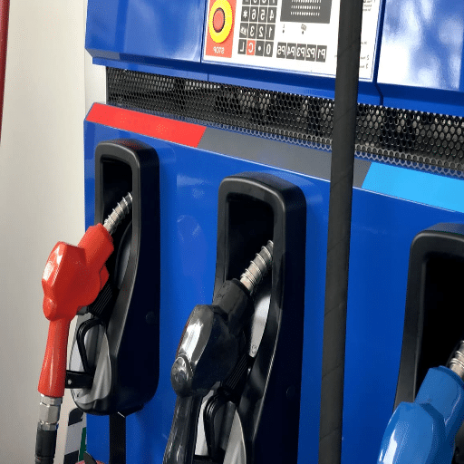
A fueling site also has multiple ignition sources. Fuel dispensers, payment terminals, canopy lights, switches, and vehicles all operate within meters of where vapor can accumulate. Without gas detection systems in place, the first sign of a problem is often a fire or an alarm from somewhere else.
The consequences extend beyond safety. A serious vapor release can trigger:
- Regulatory shutdowns and fines from the Authority Having Jurisdiction (AHJ)
- Environmental remediation costs if fuel reaches soil or groundwater
- Lost revenue while the station is closed for investigation
- Higher insurance premiums or policy cancellation
Mini-story: The Jakarta retrofit. In 2024, a fuel station in Jakarta upgraded its underground tanks but kept the original mechanical leak detector. The device monitored line pressure, but it could not detect low-level vapor accumulation in the dispenser sump.
When the local fire marshal began enforcing NFPA 30A vault vapor detection requirements, the station had to add fixed combustible gas detectors, a new alarm panel, and ventilation interlocks. The retrofit cost nearly three times what an integrated system would have cost at the time of construction. If you need to understand NFPA 30A Compliance, please read our article about NFPA 30A Compliance.
Early detection is almost always cheaper than late response. That is why gas detection systems belong in the same conversation as fire suppression, emergency shut-off, and explosion-proof electrical design.
What Gas Detection Systems Detect at Fueling Sites
Not every detector responds to every gas. The first step in selecting a gas detection system is deciding what you are trying to detect. At a fueling facility, the target gases usually fall into four groups.
Combustible Gases
These are the most common concern. Gasoline vapor, methane from compressed natural gas (CNG), propane from liquefied petroleum gas (LPG), and hydrogen all burn or explode when mixed with air in the right proportion. An LEL gas detector measures combustible gases as a percentage of the Lower Explosive Limit (LEL), which is the lowest concentration that can ignite.
Toxic Gases
Fuel vapors contain benzene, toluene, and xylene. Hydrogen sulfide can accumulate in confined spaces near tanks or separators. Carbon monoxide may build up in enclosed maintenance bays. Toxic gas detectors measure concentrations in parts per million (ppm).
Oxygen Deficiency and Enrichment
Workers entering tanks, pits, or sumps can be overcome by oxygen-poor atmospheres. Oxygen sensors are essential for confined-space entry permits and for protecting personnel in enclosed mechanical rooms.
Volatile Organic Compounds (VOCs)
VOC detectors pick up trace leaks from vapor recovery systems, hose fittings, and spill containment areas. They are often used during environmental surveys and maintenance inspections.
| Gas Category | Typical Examples | Where It Is Found | Measured In |
|---|---|---|---|
| Combustible | Gasoline vapor, methane, propane, hydrogen | Sumps, vents, fill points, compressors, fueling lanes | % LEL |
| Toxic | Benzene, H₂S, CO | Confined spaces, maintenance bays, tank areas | ppm |
| Oxygen | O₂ deficiency/enrichment | Tanks, pits, mechanical rooms | % volume |
| VOCs | Benzene, toluene, gasoline vapor | Vapor recovery, fittings, spill areas | ppm or ppb |
Gas Detector Types and Sensor Technologies

Choosing the wrong sensor is one of the most expensive mistakes when you specify a gas detection system. Understanding gas detector types is essential before you purchase any equipment. Each technology has strengths, blind spots, and maintenance requirements.
Catalytic Bead (Pellistor) Sensors
Catalytic bead sensors detect combustible gases by burning a tiny sample on a heated catalyst. The temperature change produces an electrical signal proportional to gas concentration. They are the most common and lowest-cost combustible gas detectors.
Best for: General hydrocarbon monitoring where oxygen is present, such as gasoline vapor or LPG.
Limitations: They require oxygen to function, can be poisoned by silicones or sulfur compounds, and need regular calibration.
Infrared (IR / NDIR) Sensors
Infrared sensors measure how much specific wavelengths of infrared light are absorbed by gas molecules. They are stable, poison-immune, and often last five or more years with minimal maintenance.
Best for: Hydrocarbons such as methane, propane, and gasoline vapor in harsh or oxygen-depleted environments.
Limitations: They cannot detect hydrogen or acetylene because those gases do not absorb infrared light.
Photoionization Detectors (PID)
A PID uses ultraviolet light to ionize gas molecules. It is extremely sensitive and can detect VOCs at parts-per-billion levels.
Best for: Leak detection, environmental monitoring, and tracing benzene or gasoline vapor during maintenance.
Limitations: The UV lamp and window need cleaning and eventual replacement. Humidity affects readings.
Electrochemical Sensors
Electrochemical sensors use a chemical reaction at an electrode to detect toxic gases and oxygen. They are gas-specific, accurate at low ppm levels, and low power.
Best for: Carbon monoxide, hydrogen sulfide, nitrogen dioxide, ammonia, and oxygen monitoring.
Limitations: Sensors dry out or drift over time and must be replaced according to manufacturer schedules.
Ultrasonic Gas Leak Detectors
Ultrasonic detectors listen for the high-frequency sound produced by pressurized gas escaping through a leak. They do not measure concentration; they detect the leak itself.
Best for: High-pressure CNG, LNG, or hydrogen systems where gas may escape quickly before it disperses.
Limitations: Background noise, wind, and small low-pressure leaks can reduce effectiveness.
| Sensor Technology | Best For | Gas Station Use Case | Main Limitation |
|---|---|---|---|
| Catalytic bead | Combustible gases (% LEL) | Gasoline, LPG, diesel vapor | Needs oxygen; can be poisoned |
| Infrared (IR) | Hydrocarbons | Vapor recovery, tank vents, fueling lanes | Cannot detect hydrogen |
| PID | VOCs at low ppm | Leak surveys, maintenance | Lamp maintenance; humidity sensitive |
| Electrochemical | Toxic gases and oxygen | Confined spaces, mechanical rooms | Sensor life; drift |
| Ultrasonic | Pressurized leaks | CNG/LNG/hydrogen compressors and dispensers | Background noise interference |
Fixed vs Portable vs Area Gas Detection for Gas Stations
A complete gas detection strategy usually combines more than one type of device.
Fixed Gas Detection Systems
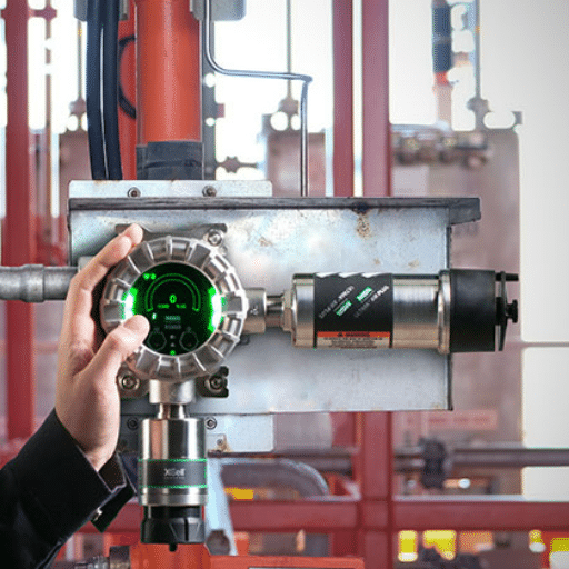
Fixed systems are permanently mounted and monitor critical zones around the clock. They are the backbone of station protection because they provide continuous coverage at high-risk points such as dispenser sumps, tank vents, and fill risers. A fixed gas detection system should be hard-wired to a central controller with alarm outputs and ventilation or shut-down interlocks.
Portable Gas Detectors
Portable detectors are carried by technicians during maintenance, confined-space entry, or leak investigation. They are essential for personal safety but should not replace fixed monitoring because they only protect the person holding them and only when they are turned on and calibrated.
Area Monitors
Area monitors are temporary or semi-permanent units used during construction, upgrades, or maintenance work. They can be placed around a hot-work zone to warn workers if a leak develops nearby.
For most retail or fleet fueling stations, the right mix is a fixed gas detection system covering permanent hazard zones, plus portable multi-gas meters for maintenance crews.
Hazardous Area Classification and Certifications
Every component of a gas detection system installed in fueling areas must be rated for the classified location. Two systems dominate the market.
NEC Class/Division System
NEC Article 514 covers motor fuel dispensing facilities. Common classifications include:
- Class I, Division 1: Flammable gases are present under normal operating conditions, such as inside dispenser sumps and near tank vent openings.
- Class I, Division 2: Flammable gases are present only under abnormal conditions, such as leaks or spills, within defined distances of dispensers and vents.
IEC/ATEX Zone System
IEC 60079-10-1 and ATEX use a zone model:
- Zone 0: Explosive atmosphere present continuously or for long periods, such as inside fuel tanks.
- Zone 1: Explosive atmosphere likely during normal operation, such as dispenser sumps and vent outlets.
- Zone 2: Explosive atmosphere not likely in normal operation and short-lived if it occurs, such as around fueling islands.
Certifications
Look for detectors and control equipment listed or certified by recognized bodies:
- UL, FM, CSA for North America
- ATEX and IECEx for Europe and most international markets
- SIL ratings (IEC 61508 / IEC 61511) when the system performs a safety instrumented function
Detectors mounted in classified areas must also use appropriate protection concepts, such as explosion-proof enclosures or intrinsically safe circuits.
Where to Install Gas Detectors at a Gas Station
Correct placement is one of the most important decisions when you design a gas detection system. Detector location is determined by gas density, ventilation, and the likely release points.
Mounting Height by Vapor Density
- Gasoline, diesel, LPG, and most hydrocarbon vapors are heavier than air. Mount detectors 6–24 inches (150–600 mm) above the floor or grade.
- Natural gas and CNG (methane) are lighter than air. Mount detectors high, near the ceiling or within 1–1.5 meters above the release source.
- Hydrogen is the lightest gas of all. Mount detectors at the highest point of the enclosure or canopy, near the ceiling.
Key Locations
- Dispenser sumps and pits: Class I, Division 1 / Zone 1; install a gas station gas detector or fixed combustible gas detector 6–12 inches above the sump floor.
- Tank vents and fill risers: Where vapor escapes during delivery; place detectors based on the fuel type.
- Vapor recovery equipment: Detectors monitor for leaks in recovery lines and processing units.
- CNG/LNG/hydrogen compressor enclosures: Install both combustible and ultrasonic detectors where pressurized gas is handled.
- Mechanical rooms and buildings: Use toxic gas and oxygen detectors for enclosed spaces.
- Loading/unloading areas: Cover the zone where tanker trucks connect and disconnect.
Placement Rules
- Keep detectors within 1–3 meters of potential leak sources when possible.
- Maintain slight overlap between detector coverage zones; typical coverage is about 7.5 meters indoors and 15 meters outdoors.
- Avoid direct airflow from vents, doors, windows, or fans that can dilute gas before it reaches the sensor.
- Keep sensors away from heat sources, electromagnetic fields, and vibration.
- Install detectors where technicians can reach them for calibration and maintenance.
Gas Detection Alarm System: Setpoints and Automatic Responses

A detector that only beeps is not enough. The gas detection system must trigger a coordinated response.
Common Setpoints
A gas detection alarm system must be configured with precise setpoints. NFPA 30A typically requires gas detection alarms at 25% of the lower flammable limit (LFL). Many systems use a two-level approach:
- Warning: 10–20% LEL, alert personnel, increase monitoring, start ventilation.
- Alarm: 25–40% LEL, activate emergency ventilation, shut off dispensers, deactivate heating systems, notify emergency response.
Automatic Actions
When gas concentration reaches the alarm setpoint, the system should:
- Sound audible and visual alarms in the affected area and at an attended location.
- Activate mechanical ventilation interlocked with the detection system.
- Shut down fuel dispensers, compressors, or other ignition sources.
- Deactivate heating systems in the space.
- Send remote notifications to operators or monitoring centers.
Fail-Safe Response
If the gas detection system itself fails, the design should default to safe conditions. Power loss, sensor fault, or communication error should all trigger the same fail-safe response. That usually means ventilation runs, heating systems turn off, and a trouble alarm sounds at an attended location.
A Seven-Step Gas Detection System Selection Workflow
Use this workflow to specify a system that matches your hazard profile and local codes.
Step 1: Identify Target Gases and Hazard Zones
List every fuel handled on site, plus any toxic or oxygen hazards in enclosed spaces.
Step 2: Classify the Area
Determine whether each location is Class I, Division 1 or 2 under NEC, or Zone 0/1/2 under IEC/ATEX.
Step 3: Choose Sensor Technology for Each Gas
Use catalytic or IR for hydrocarbons, electrochemical for toxics and oxygen, PID for VOC surveys, and ultrasonic for high-pressure gases.
Step 4: Decide Fixed vs Portable vs Area Coverage
Install fixed detectors at permanent high-risk points. Equip maintenance crews with portable meters. Use area monitors for temporary work.
Step 5: Plan Detector Locations and Mounting Heights
Place detectors based on vapor density, release points, airflow, and coverage overlap.
Step 6: Set Alarm Levels and Integrate Controls
Define warning and alarm setpoints, then wire relays to ventilation, shut-off valves, and alarm horns.
Step 7: Plan Calibration, Maintenance, and Documentation
Select calibration gas, set a test schedule, and keep records for the AHJ and your insurer.
Mini-story: The Nairobi upgrade. A project integrator in Nairobi was asked to add gas detection to an existing fueling island. The owner had already purchased low-cost combustible detectors online. The team installed them at eye level because it was convenient.
After three false alarms in one week, an engineer realized gasoline vapor collects at ground level. The detectors were relocated to 12 inches above grade, and the false alarms stopped. The lesson: placement matters as much as the detector itself.
Common Installation Mistakes That Cause Failed Inspections
Even a high-quality gas detection system can fail if it is installed incorrectly. Inspectors commonly flag these problems.
Wrong Enclosure Rating
Using a NEMA 4X weatherproof box in a Class I, Division 1 sump is a frequent mistake. The enclosure must be rated for the classified location, either explosion-proof or intrinsically safe.
Wrong Sensor Technology for the Fuel
Catalytic sensors cannot detect hydrogen. IR sensors cannot detect hydrogen. A hydrogen station that relies only on catalytic or IR detectors has a dangerous blind spot.
Detectors Mounted Too High for Gasoline Vapor
Because gasoline vapor sinks, detectors mounted on walls at head height will not see a leak until it is already widespread. Low mounting is critical.
Insufficient Coverage Overlap
Gaps between detector coverage zones create dead spots where vapor can accumulate undetected. Follow manufacturer spacing guidelines and overlap coverage slightly.
No Calibration or Maintenance Plan
A detector that is never bump-tested or calibrated will eventually drift and either miss real alarms or generate false alarms. Both outcomes erode trust in the system.
Failure to Integrate with Ventilation or Shut-Off
A detector that only sounds a local alarm relies on human response. Automated interlocks with ventilation and fuel shut-off provide faster, more reliable protection.
For a broader view of how detection connects to other safety layers, read our guide to gas station fire suppression and emergency shut-off systems.
Gas Detection System Maintenance, Calibration, and Testing

A gas detection system is only reliable if it is maintained. Every gas detection system should have a written maintenance program.
Daily Checks
- Visually inspect detectors, cables, and alarm devices for damage.
- Confirm the controller shows normal status and no fault indicators.
- Test audible and visual alarms at shift change if required by local procedure.
Weekly or Bi-Weekly Bump Tests
A bump test exposes each sensor to a known concentration of target gas to confirm it responds and alarms. It does not adjust calibration. Most manufacturers recommend bump testing every two weeks for critical applications.
Monthly Calibration Checks
Compare sensor readings to certified calibration gas. Adjust the span if the reading is outside the manufacturer’s tolerance.
Annual Maintenance
- Replace sensors that have reached end of life.
- Inspect and clean detector housings, filters, and sample lines.
- Verify relay outputs and interlocks with ventilation and shut-off systems.
- Update documentation and certificates for the AHJ and insurer.
Documentation
Keep records of every test, calibration, sensor replacement, and alarm event. Good documentation speeds up inspections, supports insurance claims, and proves due diligence if an incident occurs.
How Gas Detection Systems Fit into a Turnkey Gas Station Safety Package
Gas detection systems form the first layer of a broader safety architecture. A well-designed fueling site links detection to alarm, shut-off, suppression, and ventilation in a coordinated chain.
The typical sequence looks like this. A fixed gas detector senses rising vapor concentration. The controller sounds local and remote alarms. Relays close fuel valves or stop fuel dispensers.
If ignition occurs, fire suppression systems activate. Mechanical exhaust clears vapor from the space.
This layered approach is why detection should never be treated as a standalone accessory. Our teams design detection layouts alongside explosion-proof barriers, emergency shut-off systems, and hazardous-area electrical enclosures so every layer works together.
Mini-story: The hydrogen station surprise. A new hydrogen refueling site in Northern Europe installed catalytic combustible detectors because they were familiar and cost-effective. During commissioning, the integrator discovered that catalytic sensors respond poorly to hydrogen, and IR sensors cannot detect it at all.
The system was upgraded with thermal conductivity and electrochemical hydrogen detectors, plus ultrasonic leak detection around the compressor. The project stayed on schedule only because the issue was caught before the AHJ inspection.
If you are planning a hydrogen installation, our hydrogen refueling safety guide covers detector selection, ventilation, and ATEX/IECEx requirements in detail.
Conclusion
Gas detection systems are the early warning layer every fueling site needs. They do not replace fire suppression, emergency shut-off, or explosion-proof electrical design, but they give those systems the time they need to work.
Key takeaways:
- Match the sensor technology to the fuel.
- Place detectors based on vapor density.
- Set alarm levels that trigger automatic responses.
- Maintain the system with regular tests and documentation.
- Treat detection as one layer of a complete safety package.
Whether you are building a new station, upgrading an existing fueling island, or adding hydrogen or CNG capability, the right gas detection system protects your people, your investment, and your operating license.
Ready to design gas detection systems for your fueling site? Contact Shandong Shengrui Intelligent Equipment Co., Ltd. for a site-specific gas detection systems assessment, compliance review, and integrated equipment quote.