The tank is the easy part. It arrives as a certified, pressure-tested shell with a nameplate and a drawing. The vertical storage tank foundation underneath it is the part no tank vendor’s scope covers, and it is where a vertical tank project quietly succeeds or fails.
Most buyers receive a tank drawing and a foundation drawing with no explanation of why a ringwall was chosen over a raft. Fewer still get the numbers to check that choice against.
This guide works as a specification brief: the foundation types, the ring beam versus raft decision, soil bearing and settlement criteria, anchorage, detailing minima, and the codes that govern each. If you are still deciding on tank geometry, orientation belongs to our guide to vertical vs horizontal storage tanks; the tanks themselves are in our fuel storage tanks range.
API 650 (Welded Tanks for Oil Storage) governs vertical cylindrical flat-bottom atmospheric tanks, and its Appendix B and Annex E set the foundation and anchorage provisions this article works from.
Requirements and adopted codes differ by jurisdiction. This is a planning reference, not a substitute for your authority having jurisdiction (AHJ) or a licensed engineer’s design. Foundation design is geotechnical- and structural-engineer work.
Vertical Storage Tank Foundation Design: The Short Answer

Vertical storage tank foundation design is the selection and proportioning of the structure that carries a flat-bottom cylindrical tank’s shell, roof, and product loads into the ground without allowing settlement that distorts the shell or the bottom plate. The two most common storage tank foundation types are the reinforced concrete ringwall (also called a ring beam), which underlies the shell only, and the raft (or mat), which underlies the full plan area.
Three loads define the problem. The shell plus roof arrives as a concentrated ring load; practice literature puts that edge load at up to about 1,400 lb per lineal foot of circumference. The product arrives as a distributed load on the bottom plate. Wind, seismic, and buoyancy act as an uplift and overturning couple.
In practice, the shell-to-bottom edge is where those loads converge, and it is the critical zone on every vertical tank. The choice between a ringwall and a raft turns on diameter, soil, and settlement tolerance, not on preference.
GB 50473-2008, China’s design code for steel tank foundations, ties the ringwall line load to the roof type: a fixed roof adds roof weight to the shell load, while a floating roof delivers shell weight only. Get that wrong, and the wall section is sized for the wrong load.
The horizontal half of this problem (saddle supports, wrap angle, and support-point spacing) is a separate discipline with its own loads and governing standard, covered in our horizontal tank saddle support guide.
Ringwall vs Raft: Choosing the Vertical Tank Foundation Type
Here’s the fact that decides most ring beam vs raft foundation projects, and no vendor page states it plainly: a ringwall’s concrete quantity scales with the perimeter of the tank (roughly πD), while a raft’s scales with the area (roughly πD²/4).
Multiply diameter by four, and the ringwall’s concrete grows four times, but the raft’s grows sixteen times. Below about 20 ft (6 m) diameter, the two are close enough that a slab wins on simplicity. Above it, the ringwall pulls away, and by 50 ft the raft is usually ruled out on cost alone.
That’s the mechanism behind the “20 ft breakpoint” vendors repeat without explaining. It’s our framing, not a code rule, and it predicts the choice better than the rule does. GB 50341-2014 Appendix E lists five foundation types that cover the field, plus the pile case.
| Foundation type | Load path | When it wins | Watch out for |
|---|---|---|---|
| Reinforced concrete ringwall (ring beam) | Shell and roof weight as a line load on the wall; product spread across compacted fill | The default above ~20 ft (6 m), and wherever differential settlement is a risk. Scales with πD | Backfill compaction; hoop steel; hard to anchor for seismic uplift; thermal cracking in hot service |
| Reinforced concrete raft / mat / slab | Shell, roof, and product spread over the full plan area | Small tanks under ~20 ft (6 m); where the slab doubles as the tank bottom | Scales with πD²/4, cost-prohibitive at large diameter; only as good as the subgrade |
| Crushed-stone / granular ringwall | Shell ring bears on a compacted graded stone ring | Good soil and cost pressure, where the AHJ and listing accept it. API 650 Annex B4.3: accommodates differential settlement better than concrete because of its flexibility | Needs anti-scour protection; performance depends on field compaction |
| Granular pad, no ringwall | Shell edge load bears directly on a sand or granular cushion | Excellent bearing capacity, no uplift requirement, lowest cost | Edge cutting at the shell-to-bottom junction; washout; unpredictable underside corrosion |
| Outside ringwall | Ring sits outside the shell line with internal fill and cushion | Where the ring must also retain fill or resist sliding (GB 50341 App. E) | Uncommon in Western practice; detailing differs |
| Pile foundation / piled raft | Loads transferred through the weak stratum to a competent layer | Soft clay, marine deposits, peat; large tanks where raft thickness alone cannot meet settlement limits | Cost; pile-to-cap connection must be reliable |
The installation sequence (pad preparation, setting, and acceptance) belongs to our guide to aboveground fuel tank installation. This article stops at design.
Vertical Tank Foundation Design Criteria: What Drives the Choice
Several variables set the vertical storage tank foundation type, and they trade against each other.
| Criterion | What it changes | Typical decision |
|---|---|---|
| Tank diameter | Ringwall vs raft; whether the raft can economically span | Under ~20 ft: raft. Over ~20 ft: ringwall. Over ~50 ft: ringwall with a footing check |
| Soil bearing capacity | The footing and whether the tank can be self-anchored | Low capacity pushes toward ground improvement or piles |
| Differential settlement | Whether the chosen type is acceptable at all | Settlement, not shear strength, usually governs |
| Roof type (fixed vs floating) | The ringwall line load and the wall section | Fixed roof: shell + roof. Floating roof: shell only (GB 50473) |
| Frost depth | The embedment depth of the ringwall | The wall must extend below the frost line or the tank moves annually |
| Seismic design category | Self-anchored vs mechanically anchored; detailing prohibitions | Drives the J-ratio check, anchor count, and the hooked-bolt prohibition |
| Product temperature | Reinforcement design and insulation | Above ~93 °C (200 °F), design for the ringwall thermal moment and insulate |
One honest caveat: PIP STE030202 states that for medium tanks (20 to 50 ft diameter) the foundation type is explicitly at the foundation design engineer’s discretion. There is no formula.
Soil Bearing Capacity and Settlement Limits
Bearing Capacity
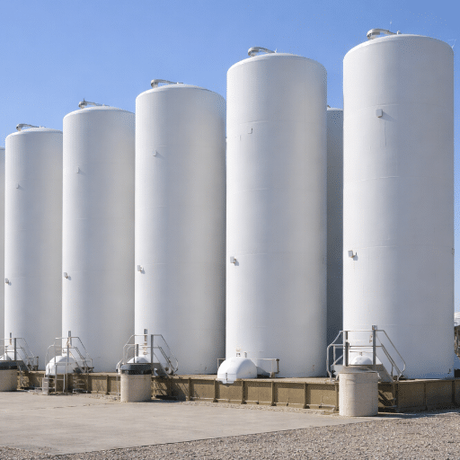
There is no universal bearing capacity for a vertical tank foundation. Every value comes from a site-specific geotechnical investigation, and the “allowable” number moves by a factor of five depending on the settlement criterion assumed.
Reported net allowable bands across real tank projects run roughly 100 to 300 kPa, with 150 to 250 kPa appearing consistently. AWWA D100 requires a safety factor of at least 3.0 on ultimate bearing for gravity loads, reducible to 2.25 with wind or seismic. California’s Title 8 §501 still caps bearing at 2,000 psf (about 96 kPa).
The classic proportioning rule is to size the ringwall so the pressure under it equals the pressure under the confined earth at the same depth, which minimises differential settlement. PIP STE030202 then admits the obvious: precise balancing is impossible, and the wall is proportioned by iteration to a practically equal pressure.
Settlement, the Criterion That Actually Governs
Tank settlement, not shear strength, decides most vertical tank foundations. Uniform settlement (the whole tank dropping evenly) raises pipe stresses but barely distorts the shell. Differential settlement (part of the tank moving relative to the rest) tears bottom plates and overstresses the shell. Out-of-plane distortion is the limit that matters.
API 650 screens with 13 mm differential per 10 m of circumference, 50 mm uniform, 1/120 edge-to-centre dishing, and tangential settlement under 1/1000. When those are exceeded, API 653 Annex B takes over: at least eight settlement measurement points at a maximum 32 ft spacing, plotted against an optimal cosine curve. A shell is sound when the fit gives R² of 0.9 or better. Permissible out-of-plane settlement follows S_max = 11L²Y / (2EH), with a differential criterion of 0.031R and a tilt limit of 1/100 of tank height, maximum 5 in.
| Parameter | Value | Source |
|---|---|---|
| Uniform settlement, hydrostatic test screening | 50 mm | API 650. Sets no structural limit, mainly affects piping and nozzles |
| Differential settlement, tank perimeter | 13 mm per 10 m of circumference | API 650; the most cited differential tolerance |
| Edge-to-centre dishing | 1/120 | API 650 Appendix B |
| Tangential settlement | < 1/1000 | Case-study literature citing API-family criteria |
| Out-of-plane evaluation | Cosine-curve fit; sound if R² > 0.9 | API 653 Annex B |
| Permissible out-of-plane settlement | S_max = 11L²Y / (2EH) | API 653 Annex B |
| Differential criterion / tilt | 0.031·R; tilt 1/100 of height, max 5 in. | API 653 |
The teaching case is a fire-water tank, 33 m diameter and 17.5 m tall. It settled 149.2 mm at maximum and 87.6 mm differentially, and passed because out-of-plane distortion measured 0.94 mm against a 34.0 mm allowable. Magnitude alone proves nothing. Buried tanks are a different regime; see our underground fuel storage tanks guide.
Ringwall Geometry, Depth, Frost, and Drainage
Three numbers decide the wall: thickness, embedment, and projection above grade.
A concrete ringwall foundation is commonly specified at 300 mm (12 in.) thick or more, with the centerline diameter set to the nominal tank diameter. NFPA 22 allows a minimum of 10 in. Where the wall is wider than it is deep, design it as an annular slab with radial flexure; past about 460 mm (18 in.) wide, consider a footing beneath it.
Embedment is set by the frost line: API-type practice puts the bottom at least 0.6 m (2 ft) below the lowest adjacent grade; PIP STE030202 requires the bottom 6 in. below the frost line and 24 in. below grade; FM Approvals 4020 requires at least 2.5 ft (0.8 m) below frost; and GB 50341-2014 prefers at least 0.6 m.
The intent is shared, and the margins are not: the required depth below frost runs from 6 in. under PIP to 2.5 ft under FM 4020, so the governing number is whichever your AHJ adopts. The top should sit at least 6 in. above grade (NFPA 22 caps it at 12 in.) and be level.
NFPA 22 §11.2.2.3 sets that levelness tolerance at 6.4 mm (¼ in.); practice tightens it to ±1/8 in. within one plate length, with no two points differing by more than ±1/4 in.
Crown the foundation 1 in. per 10 ft of radius, up to about 6 in., so the bottom plate drains outward, and provide a berm of at least 5 ft with positive drainage away from the tank. Standing water at the foundation is the beginning of underside corrosion, the failure mode that sets the service life of your carbon steel fuel storage tanks.
The Base Cushion: Sand Pad, Bituminous Cushion, and the Ringwall Fill
The layer between the tank bottom and the foundation decides how long the bottom lasts, and it is the layer most often skimped.
Inside the ringwall, compacted granular fill carries the product surcharge at 95% of maximum dry density per ASTM D698. The sand pad should be at least 4 in. thick, clean, and free of clay and earth lumps; those lumps create electrolytic cells that pit the plate from underneath.
AWWA D100-21 specifies oiled sand in detail: resistivity above 3,000 ohm-cm saturated, about 18 gallons of oil per cubic yard, with chloride under 100 ppm and sulfate under 200 ppm.
Then the 2026 update most pages miss. API 651 and NACE SP0193-2016 warn that concrete, asphalt, and oiled-sand pads trap moisture and defeat cathodic protection beneath them. NACE states that oiled tank pad materials shall not be used for new construction, and prefers clean washed sand in the 20,000 to 100,000 ohm-cm range with pH above 6.5. The oiled-sand detail that was standard practice for decades is now the detail to question.
Under the annular plate, FM Approvals 4020 calls for a 4 in. crushed-stone or clean-sand cushion, with ½ in. cane fibre or 1 in. grout between the bottom and the ringwall top, except in certain seismic zones, where steel shims must precede cement-sand grout and cane fibre is not permitted.
Anchoring Vertical Tanks for Uplift, Overturning, and Flotation

This is the highest-stakes decision on the page, and it is where API 650 foundation requirements turn into steel and concrete. It starts with a distinction that lives only inside the standard: M_rw versus M_s.
M_rw is the ringwall moment. It drives the shell compression check, the anchorage forces, and the ringwall design. M_s is the slab moment, and it drives raft soil stress and pile loads. Design an anchored raft tank using M_rw, or a ringwall tank using M_s, and every downstream number is wrong.
From there, the J-ratio decides whether you pour concrete or buy bolts. API 650 Annex E sets three bands: J ≤ 0.785 is self-anchored with no calculated uplift; 0.785 < J ≤ 1.54 uplifts but is stable provided the shell compression check passes; J > 1.54 is not stable and requires modifying the annular ring or adding mechanical anchorage.
Thickening the bottom shell course or the annular plate raises the resistance and can push a tank back under 0.785, often cheaper than a bolted anchorage. It’s the decision that most often moves a foundation’s cost. The annulus width is capped at 3.5% of diameter.
| Criterion | Value | Source |
|---|---|---|
| Anchorage ratio J | ≤ 0.785 self-anchored / 0.785–1.54 uplifting but stable / > 1.54 modify annulus or anchor | API 650 Annex E |
| Max annulus width (self-anchored route) | 3.5% of D | API 650 Annex E |
| Minimum anchor count / max spacing (seismic) | 6 anchors; ≤3 m (10 ft) | API 650 Annex E |
| Minimum bolt diameter | 1 in. (25 mm) + corrosion allowance; 1¼ in. (32 mm) on ringwall | API 650 §5.12 / NFPA 22 §11.4.3.3 |
| Anchor strap | ≥6 mm thick, ≥1.5 mm per surface corrosion allowance | API 650 Annex E |
| Prohibited in seismic design | Hooked L/J bolts; bond- or friction-only anchors | API 650 Annex E |
| Overturning stability / bolt stress | Ratio ≥2.0; allowable 0.8 F_y (33% increase for wind/seismic) | API 650 §5.12 / Annex E |
Two of those rows are inspection failures waiting to happen. Hooked L- or J-shaped embedded bolts, and anchors relying only on bond or friction, may not be used where seismic design is required. Neither may cane fibre under the shell in certain seismic zones. Both appear on drawings that look correct.
Flotation is the other uplift case. Design on the buoyancy of an empty, fully submerged tank, and you may count concrete, soil, and water above the foundation as resisting. The net uplift checks, U = P_WR·D²·4.08 + (4·M_WH/D) − W₂ for wind, and U = (4·M_rw/D) − W₂(1 − 0.4A_v) for seismic, are the first numbers a design review runs before you pour.
Reinforcement, Concrete, and Detailing Minima
Concrete is commonly specified at 3,000 psi (about 20.7 MPa) minimum at 28 days per PIP STE030202, with reinforcement following ACI 318 and API 650 Appendices B, E, F, and I.
Hoop steel resists lateral earth pressure: assume at least 50% of the combined vertical fluid and soil pressure, or 30% with granular backfill, and do not credit passive pressure. ACI 318 Chapter 14 sets hoop steel at 0.0020 with #5 or smaller Grade 60 bars (otherwise 0.0025), vertical steel at 0.0012 (otherwise 0.0015), with a maximum spacing of 18 in. GB 50341-2014 sets the hoop reinforcement total ratio at ≥0.4%, the same target by a different route.
| Detail | Commonly specified value | Source |
|---|---|---|
| Concrete strength | ≥3,000 psi (20.7 MPa) at 28 days | PIP STE030202 |
| Ringwall thickness | ≥300 mm (12 in.); NFPA 22 min 10 in. | GB 50341 / NFPA 22 |
| Projection above grade | ≥6 in. (NFPA max 12 in.) | PIP / NFPA 22 |
| Levelness | 6.4 mm (¼ in.); practice ±1/8 in. within a plate length | NFPA 22 §11.2.2.3 |
| Hoop steel from earth pressure | ≥50% of vertical (30% granular); passive excluded | PIP STE030202 |
| ACI 318 Ch. 14 minima | Hoop 0.0020 / 0.0025; vertical 0.0012 / 0.0015; spacing ≤18 in. | ACI 318 |
Finally, one gap to respect: codes stipulate the annular plate’s width, thickness, and projection beyond the shell weld, but supply no stress equations. The plate-flexure interaction with the ringwall is design work, not a lookup.
Hot Service, Cold Climates, and Difficult Ground

Above about 93 °C (200 °F), the vertical storage tank foundation itself changes. Soil moisture evaporates, driving non-uniform settlement, and the ringwall develops a moment from the temperature difference between its top and bottom that can crack the concrete and lose tank support.
API 650 Annex B adds a subtler effect: in elevated-temperature service, differential settlement develops between the ringwall and the soil under the tank bottom beside it, as the soil shrinks non-uniformly. GB 50341-2014 requires an insulating layer where the tank bottom contacts the foundation above 90 °C. The cold hydrostatic test does not reproduce any of this; a ringwall carrying heated product can develop vertical cracking on its outer face within a few years, from a thermal moment that never appears on a mild-service drawing.
By contrast, cold climates are simpler but less forgiving. Frost heave is the reason the ringwall extends below the frost line; it is a failure mode, not a formality.
Difficult ground is where the raft’s limits show. For large tanks (diameter beyond about 40 m) on soft clay with undrained shear strength at or below 12 kPa, ground improvement or a piled raft is required, because raft thickness alone cannot meet settlement limits. Buried cavities make it worse: one documented case saw surficial voids push settlement to 400% of prediction. The geotechnical investigation is the design; everything after it is arithmetic.
For more information, please read our article on horizontal tank saddle supports.
Common Mistakes and How to Avoid Them
Here are eight decisions that cost more than they save:
- Designing from the tank drawing alone, without a geotechnical investigation. There is no bearing number in a tank drawing.
- Taking the ringwall above the frost line to save one course of concrete. The tank will move every winter.
- Assuming a raft is cheaper at large diameter. Its concrete scales with diameter squared, not diameter.
- Running a J-ratio above 1.54 and hoping the shell compression check rescues it. It won’t.
- Specifying hooked anchor bolts where seismic design applies. They’re prohibited.
- Leaving cane fibre under the shell in a seismic zone. Same failure.
- Packing grout into a detail that needs to move. The detail cracks instead.
- Ignoring drainage. Standing water at the foundation is the beginning of underside corrosion.
Frequently Asked Questions
Ring beam vs raft foundation for storage tanks, which should I use?
Use a ring beam (ringwall) above roughly 20 ft (6 m) diameter, and a raft below it. Ringwall concrete scales with the tank perimeter, while raft concrete scales with the plan area, so the raft becomes disproportionately expensive as diameter grows. Soil and settlement tolerance can override this.
Do vertical tanks need a different foundation than horizontal tanks?
Yes. A vertical flat-bottom tank needs a ringwall or raft, governed by API 650. A horizontal tank sits on saddles over pads, governed by its listing such as UL 142. The load paths and governing standards differ.
What soil bearing capacity does a vertical tank need?
There is no universal value. Reported net allowable bands run roughly 100 to 300 kPa, but every figure is site-specific and settlement, not shear strength, usually governs. A geotechnical investigation is the only source of a real number.
How much differential settlement is acceptable for a storage tank?
API 650 screens at 13 mm differential per 10 m of circumference, with 50 mm uniform and 1/120 dishing. Beyond that, API 653 Annex B evaluates out-of-plane distortion against an optimal cosine curve, requiring R² above 0.9. Out-of-plane distortion, not total settlement, is the criterion.
How thick and how deep should a tank ringwall be?
Commonly 300 mm (12 in.) or thicker, with NFPA 22 permitting a 10 in. minimum. Depth is set by the frost line: API-type practice uses at least 0.6 m (2 ft) below adjacent grade, PIP requires 6 in. below frost and 24 in. below grade, and FM Approvals 4020 requires 2.5 ft.
Does a tank foundation need to be below the frost line?
Yes. A ringwall that stops above the frost line lets the ground freeze and heave beneath it, moving the tank every winter. PIP, FM Approvals 4020, and GB 50341-2014 all set an embedment below the frost line for this reason.
Does a vertical storage tank need to be anchored?
Only when the J-ratio in API 650 Annex E says so. J ≤ 0.785 needs no calculated uplift anchorage; 0.785 < J ≤ 1.54 is stable if the shell compression check passes; J > 1.54 requires modifying the annular ring or adding mechanical anchors. Anchors must also resist flotation of an empty, submerged tank.
How much does a vertical storage tank foundation cost?
No universal per-tank figure exists, because cost is driven by concrete volume, soil conditions, and geotechnical requirements. Reference points: design fees commonly run $750 to $1,500, and concrete pad work around $5.00 to $6.75 per cubic foot. For an accurate number, price the concrete volume from a stamped design.
Requirements vary by jurisdiction, code edition, and tank listing. This article is a planning reference, not a substitute for your AHJ’s requirements or a licensed engineer’s design.
Conclusion
Vertical storage tank foundation design is decided long before the tank arrives, and the choices do not transfer between sizes. Five takeaways:
- The foundation is where the project’s risk concentrates, and it is the one scope the tank vendor’s drawing stops short of.
- Ring beam versus raft is a cost-geometry decision, perimeter against area. Understand the mechanism, and the 20 ft breakpoint stops being a rule you repeat.
- Settlement, not bearing strength, usually governs. Uniform settlement is nearly harmless; out-of-plane distortion is the limit that fails tanks.
- The J-ratio decides whether you pour concrete or buy anchor bolts. Thickening the annular plate is often the cheaper route.
- Frost depth, drainage, and the base cushion are the cheap details that decide how long the tank lasts, and the oiled-sand pad you may have specified is now out of favour for new construction.
Whichever vertical storage tank foundation type your site selects, request a design review and our engineering team will work through the civil and structural interface with your engineer of record, from bearing and settlement to anchorage and the base cushion. Our fuel storage tanks ship with documentation and drawing packages suitable for AHJ and geotechnical submittals, because the tank vendor’s drawings should not be where your support ends.