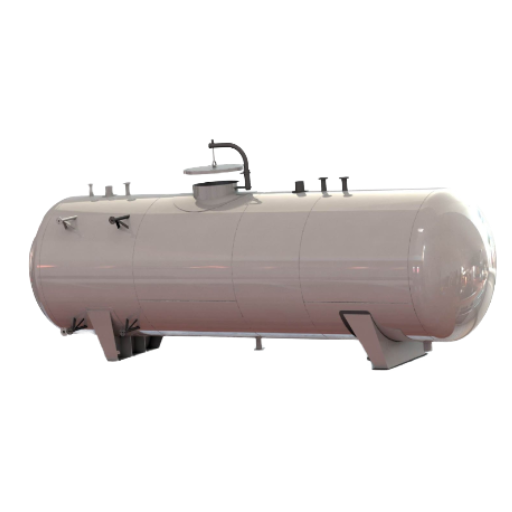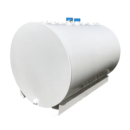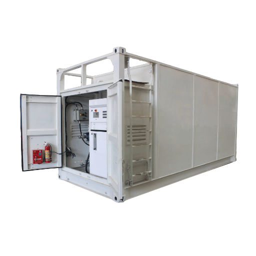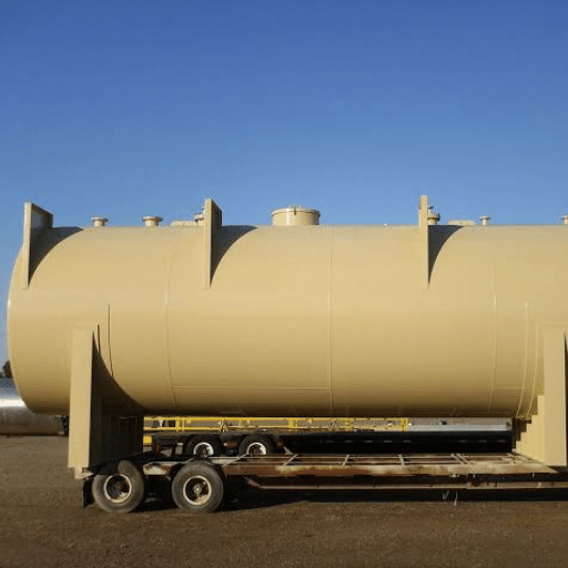
A terminal planner fit six 20-metre tanks into a tidy two-by-three grid, sent the drawing for review, and got it back with a single line circled. The containment bund, not the tanks, needed more floor area than the plot allowed.
If you have laid out more than two storage tanks on one site, you know that feeling. Inter-tank spacing is the easy part of tank farm layout design. The hard part is everything stacked on top of it: the bund, the number of rows, the road a fire truck needs, and the direction a spill will run.
This guide covers the full tank farm layout design method. You will learn how tanks are arranged, how big a containment bund must be, the maximum capacity one enclosure may hold, and the arithmetic that tells you how many tanks fit.
Here is what we cover:
- The inputs that drive every layout decision
- Tank arrangement and the two-row rule
- Bund (dyke) sizing, height, and freeboard
- Aggregate capacity limits by roof type
- Plot dimension arithmetic with a worked example
- Access roads and spill flow direction
One note before the numbers. Layout is a licensed engineer deliverable, and the code that applies to you is whichever your local authority having jurisdiction (AHJ) has adopted. Use this guide to plan, then confirm every figure locally.
If you only need setback distances, our spacing and setback guide has them. This article is a different job: arranging several tanks on one plot. If you are still deciding on tank geometry, orientation belongs to our guide to vertical vs horizontal storage tanks.
Tank Farm Layout Design: The Short Answer
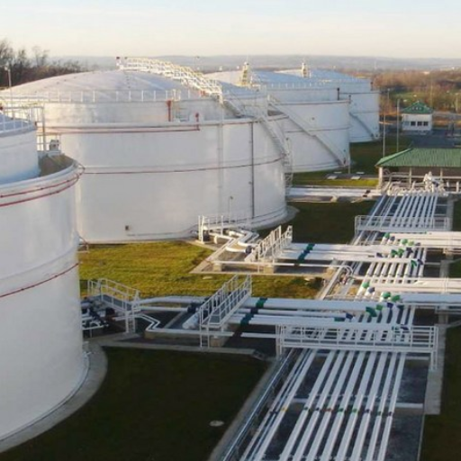
Tank farm layout design, often shortened to tank farm design, is the arrangement of multiple storage tanks and their containment on a site. In a bulk depot or a full oil terminal layout, it fixes the tank rows and grid, the inter-tank and tank-to-bund distances, the diked enclosure size and subdivision, the aggregate capacity per bundle, the access roads, and the downwind placement that keeps spills away from ignition sources.
Three questions decide everything else:
- How are the tanks arranged? The rows, the grid, the pitch.
- How are they contained? The bund size, subdivision, and freeboard.
- How many fit? The plot dimension arithmetic.
The rule that ties these together is simple. The governing code is whichever your jurisdiction adopted. In the United States, that is usually NFPA 30 and API 2610. In India, it is OISD-STD-118 and the PNGRB technical standards. In China, it is GB 50160, and in the United Kingdom and the EU, EN 14015 and CIRIA guidance.
The Layout Inputs: Codes, Products, and Site Constraints
Before you draw a single rectangle, six inputs must be fixed. Miss one and the plot plan changes underneath you.
- The governing code. Local adoption decides the numbers.
- The product class. Class I, II, IIIA, and IIIB flammable and combustible liquids each carry their own regime. Liquefied petroleum gas (LPG) has its own rules again.
- The roof type of every tank. Fixed cone, internal floating, external floating, or dome. Roof type changes both spacing and the aggregate capacity a bund may hold.
- Tank diameter and height. These two numbers drive every distance and the plot area.
- Site constraints. Topography, grade, prevailing wind, adjacent property, and existing structures.
- Drainage and expansion. Where the spill outfall goes, and where the next tank might someday sit.
Most checklists cover the first five. They skip the sixth, yet drainage direction and future expansion are two of the most common reasons a good layout fails review. Spacing is an input here, not the subject. Which distance applies to a building or boundary is a separate question, covered in our aboveground tank spacing guide.
Tank Arrangement: Rows, Grids, and the Two-Row Rule
Tanks in a diked enclosure are arranged in a maximum of two rows, so that every tank can be approached by road from around the enclosure. That rule appears in OISD-STD-118 and the PNGRB technical standards.
| Rule | Value | Source |
|---|---|---|
| Maximum rows in a diked enclosure | 2 rows, so every tank is road-approachable | OISD 118 Cl. 7.1.1; PNGRB T4S |
| Single-row trigger | Tanks ≥50,000 m³ | OISD 118 |
| Common block sizes | 2×2 and 2×3 | Process-plant layout guidance |
| Block to avoid | 3×3, where interior tanks are not road-approachable | Process-plant layout guidance |
| Pitch geometry | Square or triangular (staggered) | PNGRB; industry guidance |
| AHJ override | 3+ rows or irregular pattern may require greater spacing | NFPA 30 |
| Adjacent groups sharing a bund wall | Nearest tank ≥15 m from inside top of adjacent group’s bund | OISD 118 |
| Separate diked enclosures | ≥ larger diameter or 30 m, whichever is more | PNGRB |
One exception: tanks of 50,000 m³ and above are laid in a single row, not two. A block three tanks deep shields interior tanks from firefighters, so the workable blocks are two by two and two by three. A three-by-three block is unacceptable because no interior tank can be reached by road. The code says the same in reverse: where Class I or Class II tanks sit in three or more rows or in an irregular pattern, the AHJ may require greater spacing to keep interior tanks accessible (NFPA 30).
On pitch, square spacing lines up neatly with pipe manifolds and road grids, while triangular, or staggered, spacing packs more shell area into the same rectangle but complicates the road network. Choose one early, because it sets the whole drawing. Group compatible products, and keep incompatible ones apart: do not mix crude and LPG in a single bund, but separate them with an internal firewall. Tank shape feeds in as well: horizontal tanks need clear room for horizontal tank saddle supports.
A cautionary case. A depot team once packed tanks three deep to save land, and the plan was rejected at review because the middle row had no road frontage. Adding one row of separation cost less than the redesign that followed. Two rows is an access rule, not a preference.
For multi-compartment tanks that divide one shell rather than several separate tanks, our guide to multi-compartment fuel storage tanks covers that layout instead.
Inter-Tank Spacing: What the Layout Inherits
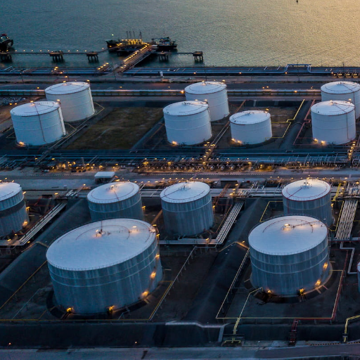
Tank farm spacing is measured shell to shell, and the baseline rule is one sixth of the sum of the two adjacent tank diameters, with a minimum of 3 ft (0.9 m) for tanks up to 150 ft (45 m) in diameter (NFPA 30 §22.4.2.1).
Roof type then adjusts it. Industry sources commonly cite 0.5 times the larger diameter for fixed cone roof tanks and 0.4 times for floating roof tanks, each with a 15 m minimum. Treat those fractions as guidance rather than gospel. Published values vary by source and edition, and your AHJ governs.
Those full-capacity-based setback tables sit in our spacing and setback guide. Here we care about one consequence: inter-tank spacing is a term in the plot formula below, so it directly sets how much land the farm consumes.
Tank Bund Design and Dyke Enclosure Design
A bund is the tank farm’s secondary containment: it holds the spill. Getting its size and shape right is the single largest driver of plot area.
Start with terminology, because three words describe the same duty:
- Bund is the UK and Australian term for an engineered, impermeable containment wall around a tank group.
- Dike or dyke is the United States (NFPA) and Indian (OISD) term for the same thing. An earthen dyke is the embankment form used at large farms.
- Firewall or intermediate dike is a low internal wall that subdivides a bund.
Two numbers define a bund: its height and its freeboard. The rest of the enclosure follows from them.
| Parameter | Common value | Standard / source |
|---|---|---|
| Bund wall height (above interior grade) | 900–1,800 mm (3–6 ft) | Industry practice; project specs ≥1 m, ≤2 m. NFPA 30 caps the average interior height at 6 ft (1.83 m) |
| Preferred height | Under 1.5 m | Low walls avoid obstructing firefighters and ease escape |
| Freeboard (above calculated liquid level) | 200 mm | OISD 118 / PNGRB |
| Freeboard for firefighting water | ≥100 mm, 250 mm surge | CIRIA C736; project specs often 200–300 mm |
| Enclosure capacity basis | 100% of largest tank | NFPA 30 §22.11.2.2; GB 50160 (100% + rainfall). Deduct other tanks’ volume below dike height |
| Industry capacity convention | 110% of largest tank | CIRIA C736; UK/HSE practice, not NFPA 30 |
| Tank shell to inside toe of bund | ≥ half tank height; practically 3–7 m | PNGRB 4.1.5.4; a bund set too close traps heat |
| Firewall (multi-tank bund) | ≥600 mm height | OISD 118 / PNGRB; small tanks ≤9 m dia and ≤5,000 kL total count as one tank |
| Dike toe to buildable property line | ≥10 ft (3 m) | NFPA 30 §22.11.2.3; additive on top of the tank setback |
The certification behind a self-bunded tank is covered in our guide to self-bunded fuel tanks.
Aggregate Capacity Limits: How Much One Bund Can Hold
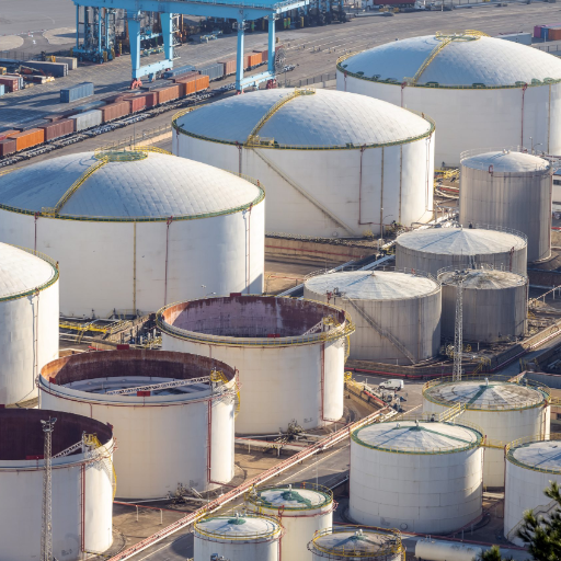
You cannot fill a bund with unlimited tank capacity. Every regime sets a ceiling, and the ceiling depends on roof type. The two dominant systems take different routes: OISD and PNGRB set one flat cap, while NFPA 30 uses subdivision.
| Standard / regime | Roof type | Aggregate capacity limit per diked enclosure |
|---|---|---|
| OISD-STD-118 / PNGRB (India) | Fixed cone roof (incl. fixed-cum-floating) | 60,000 m³ |
| OISD-STD-118 / PNGRB (India) | Floating roof (internal or external) | 120,000 m³ |
| OISD-STD-118 (India) | Single tank ≥50,000 m³ | Laid in a single row |
| NFPA 30 (US) | Stable liquids, one subdivision | No tank >10,000 bbl (420,000 gal); aggregate ≤15,000 bbl (630,000 gal) |
| NFPA 30 (US) | Stable liquids, per tank | One subdivision for each tank >2,380 bbl (100,000 gal) |
| NFPA 30 (US) | Stable liquids, small-tank group | No tank >2,380 bbl; aggregate ≤3,750 bbl (150,000 gal) |
| NFPA 30 (US) | Class I liquids, common diked area, any tank >150 ft (45 m) dia | Intermediate dikes holding ≥10% of the enclosed tank’s capacity |
A fixed-cum-floating group counts as fixed roof unless the fixed-roof tanks have unobstructed shell windows. The design lesson is identical in both systems: roof type sets how much capacity one bundle may hold. A floating roof limits vapour space and fire exposure, so the code permits a larger aggregate behind one wall.
Two spacing rules matter when bundles sit side by side. Where two groups share a common bund wall, the nearest tank must sit at least 15 m from the inside top of the adjacent group’s bund. Tanks in separate diked enclosures need at least the larger of the two diameters, or 30 m. Confirm these thresholds against the edition your AHJ has adopted.
Plot Dimension Arithmetic: How Many Tanks Fit in a Tank Farm?
This is where the constraints of a tank farm layout design become a drawing. For a rectangular grid of r rows and c columns of tanks of diameter D, with inter-tank distance d₁ and shell-to-bund distance d₂:
- Plot length: L = r × D + (r − 1) × d₁ + 2 × d₂
- Plot width: W = c × D + (c − 1) × d₁ + 2 × d₂
- Plot area: A = L × W, compared against the bund volume area A₂, which is the required containment volume divided by bund height. Take the larger.
Now run it. Six tanks, D = 20 m, arranged in two rows by three columns. Inter-tank spacing d₁ = 10 m, shell-to-bund d₂ = 5 m.
- L = 2 × 20 + 1 × 10 + 2 × 5 = 60 m
- W = 3 × 20 + 2 × 10 + 2 × 5 = 90 m
- A = 60 × 90 = 5,400 m² as drawn
Now check containment. To hold 100 to 110 percent of one 20 m tank’s volume at a 1.5 m bund height, the required bund floor area may exceed the 5,400 m² the grid occupies. When it does, the bund governs, and the plot grows.
The story of the bund that set the site. The planner in our opening had exactly this case. The tank grid fit comfortably, but the containment volume pushed the enclosure wider than the tanks by a third. The tanks were never the constraint. The bund was. This is why layout and containment cannot be designed in separate meetings.
To estimate how many tanks a site will hold, divide the usable site area by A, then apply the aggregate capacity cap from the previous section and the two-row rule. All three constraints must pass. If they do not, the site is oversubscribed. Tank type adds one more floor: see our guide to vertical storage tank foundations.
One bridge: the volume each tank must hold comes from the sizing method, not the layout. Our guide to how to calculate fuel tank capacity covers that formula.
Access, Roads, and Firefighting Reach
Access is a design requirement, not an afterthought. A layout that cannot be reached in a fire is not a layout.
- Roads on all four sides of every diked enclosure, interconnected with the roads of adjacent enclosures, so access survives even if one route is cut by fire.
- No cul de sacs. Use a uniform grid, and give each block at least two approach directions.
- Widths. Major roads at least 6 m, minor roads at least 4 m, footpaths around 0.6 m, and vehicular ways within units around 4.0 m. A major road should not run more than about 400 m without a turnaround.
- A clear lane. Keep roughly a 6 m clear lane around the farm for fire trucks.
Around the bund, place firefighting screens and steps so crews can approach safely. A foam system must reach every tank shell, so position the fire water tank to feed by gravity.
For the build sequence that follows a layout, see our guide to aboveground fuel tank installation. And if you want a second set of eyes on your access plan, our engineering team can review your site plan before you submit.
Downwind Placement, Spill Flow, and Grade
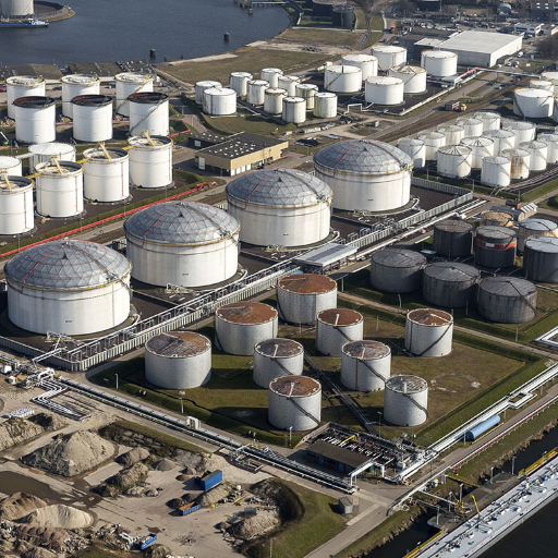
Layout is also a question of direction, and this is where many plans quietly fail.
Wind drives vapour. Locate tanks downwind of process units and ignition sources, keep the control room upwind and outside the vapour dispersion zone, and set loading and unloading areas downwind or crosswind.
Gravity drives spills. A tank farm should not sit at a higher level than the process units in the same catchment, and a flammable spill must not flow toward a process area or an ignition source. Directional grading is a layout decision, not a civil detail. Slope the enclosure away from the tanks to a sump, and route minor spills and rainwater to a treating pond.
Two more rules protect the drainage. Isolation valves belong outside the bund, so controls stay reachable from outside the dike under fire. Pipe through an earthen dike should be coated and wrapped; pipe through a concrete dike should be sleeved. Run piping outside the dyke, not through a neighbouring enclosure.
The spill that ran the wrong way. A site once graded its enclosure so a spill drained toward an adjacent area that held ignition sources. The tanks were spaced correctly, and the bund was the right size, but the plan was rejected on flow direction alone. Regrading and moving the tanks downwind delayed the project by months. Direction is part of the drawing.
Frequently Asked Questions
How many tanks fit in a tank farm?
Divide usable site area by the plot area from the formula, then apply three constraints: the two row rule, the aggregate capacity cap per bund (60,000 m³ fixed roof, 120,000 m³ floating roof under OISD), and the inter-tank spacing. If all three pass, the count stands.
How far apart should storage tanks be in a tank farm?
The baseline is one-sixth of the sum of the two adjacent diameters, with a 3 ft (0.9 m) minimum, adjusted by roof type and capacity. The full setback tables are in our spacing and setback guide.
What is the maximum number of rows of tanks?
Two rows, so every tank can be approached by road. Tanks of 50,000 m³ and above are laid in a single row.
How high should a bund wall be?
Typically 900 to 1,800 mm above interior grade, with NFPA 30 capping the average interior height at 6 ft (1.83 m). Low walls under 1.5 m are preferred for firefighting access.
How much freeboard does a bund need?
At least 200 mm above the calculated liquid level under OISD and PNGRB, or 100 mm for firefighting water with 250 mm surge under CIRIA C736.
What is the difference between a bund and a dyke?
Bund is the UK and Australian term; dike or dyke is the United States and Indian term for the same containment duty. An earthen dyke is the embankment form.
How many tanks can sit in one containment area?
That depends on the aggregate capacity cap for the roof type, and on whether the tanks are independent or share a self-bunded shell.
Conclusion
Tank farm layout design is where separate decisions become one land area. Keep five takeaways in view:
- Arrange tanks in a maximum of two rows so every tank is road-approachable, with a single row above 50,000 m³.
- Sizing the bund usually sets the final land area, not the tank grid.
- Roof type sets the aggregate capacity a bund may hold: 60,000 m³ fixed roof, 120,000 m³ floating roof under OISD.
- The plot formula turns spacing, diameter, and bund distances into an area you can test against the site.
- Downwind placement and spill flow direction are layout decisions, not civil afterthoughts.
Layout is a licensed engineer deliverable, and we supply the tanks and bunding components that sit inside it. If you are planning a depot, a fleet fuelling site, or a bulk storage area, send us your site plan and tank list. We will help you review the layout and match the right storage tanks to your plot.
Browse our fuel storage tanks to see the range that fits most layouts, and the vertical versus horizontal tank options that set your footprint.