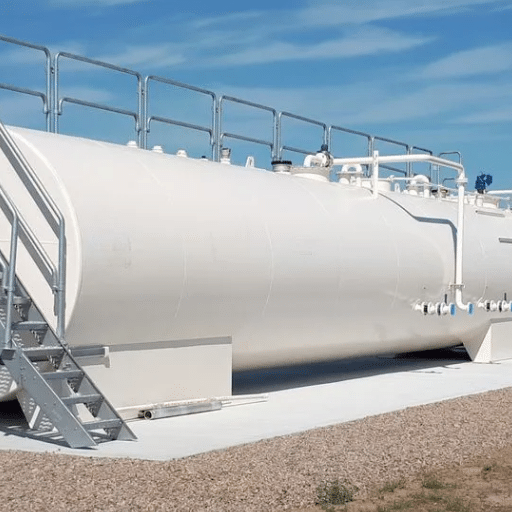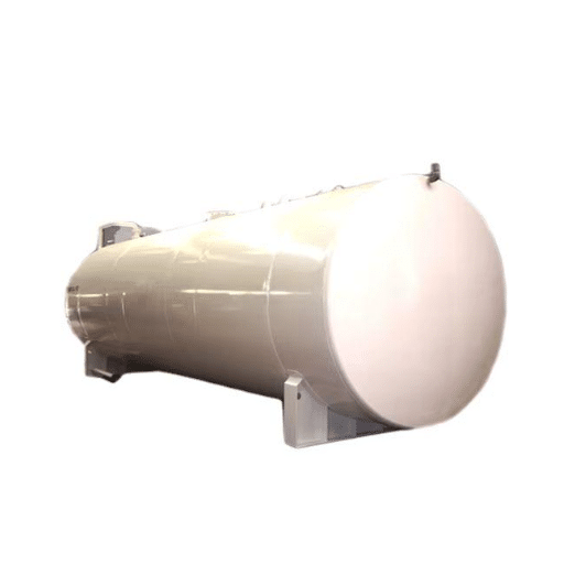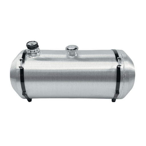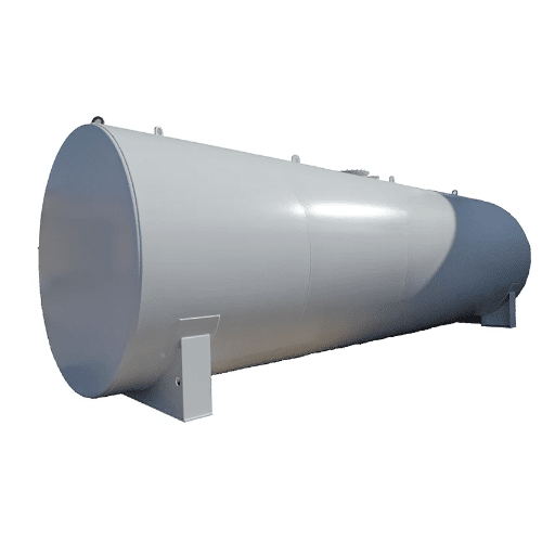
The tank looks like the expensive part of the purchase. The two pads underneath it, and the foundation beneath those, quietly decide whether the tank is still serviceable in thirty years.
Vendor literature states saddle dimensions and stops there. It seldom explains how saddle spacing is chosen, when a continuous support beats two saddles, how the tank is allowed to move, or what the foundation must carry.
This guide treats horizontal tank saddle support and foundation design as a specification brief: what a saddle does, how spacing is decided, fixed versus sliding saddles, anchoring, and how to size the foundation under it. Tank orientation belongs to our guide to vertical vs horizontal storage tanks.
Requirements and adopted codes differ by jurisdiction. This is a planning reference, not a substitute for your authority having jurisdiction (AHJ) or a licensed engineer’s design. Support and foundation design is engineer-of-record work.
Horizontal Tank Saddle Support: The Short Answer
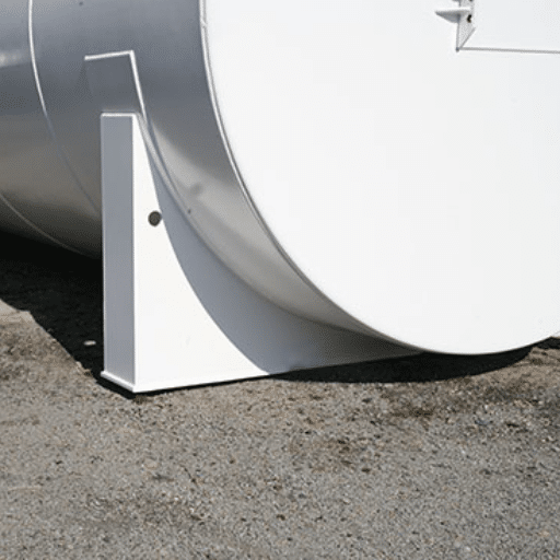
A horizontal tank saddle support is a curved steel cradle that carries a horizontal cylindrical tank at two discrete points, transferring the tank’s weight and contents into the foundation below. Two saddles are standard because the reactions become statically determinate: with two supports, the load at each point is predictable without analyzing how the tank and the foundation share deflection.
Nothing scales from a 1,000-gallon day tank to a 50,000-gallon depot tank. Spacing, saddle width, wear-plate size, and bearing area all grow with the load. Flat-bottom vertical tanks bear directly on their foundation and need a ring beam or a slab, not saddles; a horizontal cylinder touches the ground along two arcs only, so it needs supports built for point loading.
What a Saddle Support Does, and How It Is Built
The Anatomy of a Saddle
Four parts do the work.
The wear plate, also called the reinforcement pad or saddle top plate, is welded to the shell and spreads the local load into it. The saddle web carries the reaction down to the base. The base plate bears on the foundation and receives the anchor bolts. Stiffeners brace the web where the reaction is large, or the saddle is tall.
The contact arc matters as much as plate thickness.
The saddle should wrap the shell through at least 120°, with 120° to 150° in common practice, and some standards require a 150° series for small-diameter tanks. A narrow wrap concentrates the reaction into too little shell. The saddle’s radius should sit roughly 1% to 2% larger than the shell, so the tank bears on the horn line rather than jamming against the plate across its whole arc.
Clearance, Inspection, and Fire Protection
Clearance under the shell is a maintenance and a compliance decision. The threshold is hard.
| Clearance under shell | Fire protection of the support | Notes |
|---|---|---|
| About 4–6 in. | None required | Common minimum for underside visual inspection |
| 6 in. (standard) | None required | Standard vendor saddle height for UL-142 tanks |
| Up to 12 in. | None required | Steel saddles less than 12 in. high need not be fire-protected |
| Above 12 in. | 2-hour fire-rated protection required | Or an accepted equivalent; some jurisdictions accept water spray |
Two things drive those numbers.
Elevation lets someone see the underside of the shell, where a tank on damp concrete corrodes first and invisibly. Fire protection attaches to height instead: a support under 12 inches is low enough that a pool fire beneath the tank is unlikely to threaten the shell through it. Build taller for drainage, and you have crossed into a protected-support requirement. That is an inspection item, not a preference.
How Saddle Spacing Is Decided
Saddle spacing is a compromise.
Push the saddles apart and the tank sags between them, so midspan bending grows. Pull them together and the end overhangs grow, so local stress at each saddle rises. The engineer trades one stress against the other. Four rules frame the decision:
- Spacing is held to about 1.5 times the tank diameter or less. Treat this as a rule of thumb, not a code value.
- The overhang beyond each end saddle roughly equals half the spacing, so the tank sits symmetrically.
- The distance from a saddle centerline to the head tangent, written A, should not exceed about 0.25 times the tank length L. Published optima disagree: some work puts the best point at A/L = 0.25, other work at 0.10 to 0.15. The optimum depends on shell geometry.
- China’s NB/T 47042-2014 caps A at 0.5 times the head radius and at 0.2 L, and requires one saddle to be free to slide or roll.
Why two saddles and not three? Two reactions are statically determinate. Finite-element work on three-saddle arrangements found peak tensile stress near the center saddle 240% higher than in the equivalent two-saddle case. A third support adds restraint where the tank wants to sag, plus a third foundation that settles differently from the other two.
Then the engineer runs the local checks.
Zick analysis, published in 1951, remains the classical method, producing five results: longitudinal bending at midspan and over the saddle, tangential shear, circumferential bending at the saddle horn, and ring compression. Its limits matter. Zick holds within roughly 25% for typical thickness, length, and radius bands, but under-predicts for short, large-diameter vessels. ASME Section VIII Division 1 contains no complete saddle design procedure, which is why PD 5500 Annex G and EN 13445 §16.8 are used alongside it.
Two levers cut local stress. A fixed wear plate of the same thickness as the shell, extending at least 5° above the saddle horn, reduces peak horn stress by 15% to 40%. Omit it only when horn circumferential stress stays below 1.5 times allowable and ring compression stays below half of minimum yield, and never in a seismic region. Saddle width is the second lever: stress falls as the saddle widens to about 2.0 m, with no benefit beyond roughly 3.0 m.
Picture a 40-foot horizontal tank specified with three saddles “for safety.” The center support raised peak stress sharply at midspan. The third footing then settled differently from the other two, so the tank carried a bending moment nobody designed for. Two saddles were never a limitation. It was the design.
Two Saddles or a Continuous Support?

| Support configuration | Load path | Governing checks | When it wins | Watch out for |
|---|---|---|---|---|
| Two discrete saddles on piers or footings | Two point loads, statically determinate | Shell stress at the horn, ring compression, base plate, footing bearing | Default for UL-142 tanks; listed, inspectable, allows thermal movement | High local stress, so wear plates are usual; needs two good foundations |
| Two saddles on a continuous skid | Two point loads over a longer bearing length | Skid bending, bearing, anchorage | Shop-packaged units, container stations, temporary sites | The skid must be designed; plan drainage under it |
| Continuous ring or cradle | Distributed load, statically indeterminate | Shell stress distribution, thermal restraint, weld, settlement | Large or heavy horizontals needing minimum local stress | Restrains thermal movement, blocks underside access, changes the regulatory picture |
That last column deserves a plain statement. For horizontal aboveground tanks, no more than two longitudinal points of support are permitted unless the tank sits on continuous skids welded to pads. California’s Title 8 §501 writes it that way. Past two supports, the reactions stop being predictable, and the tank starts bridging between foundations that do not move alike.
Skid-mounted units are the common route around the limit, and the skid is a structure, not a pallet.
Fixed vs Sliding Saddles: Designing for Thermal Movement
A horizontal cylinder grows when it warms up. Warm fuel, sun on the shell, and seasonal ground temperature all push the tank slightly longer along its axis and slightly wider around it. The movement is small, single-digit millimeters, but it is not zero, and it has to go somewhere.
Restrain that growth at both saddles, and the tank fights its own foundation, loading the shell and the anchor bolts instead. So the rule is one saddle fixed, one saddle free. The fixed saddle is bolted and grouted. The sliding saddle moves in the longitudinal direction.
The mechanism that makes it work is the hole shape. The sliding saddle’s base plate carries slots elongated in the longitudinal direction, with keeper plates or plate washers so the nut clamps the plate without seizing. A drawing that says only “slotted holes” is not enough: slots running across the tank rather than along it do nothing, and that is a classic field error.
Four detailing points keep the sliding saddle from becoming a fixed one by accident:
- Do not over-tighten the sliding-saddle nuts. Over-torque clamps the plate and defeats the slot.
- Keep a no-grout zone under the sliding saddle. Grout only under the fixed saddle.
- Do not clamp the sliding saddle with a rigid guide. Use separated stops and a low-friction surface where movement is large.
- Inspect the sliding saddles periodically. They work only if they can actually slide.
One installation had both saddles fully torqued down on packed grout. Nothing looked wrong. The tank’s growth had nowhere to go, so it loaded the shell and the bolts instead. Repairing it meant jacking the tank, and the fix cost far more than the detailing it replaced.
Have our engineers review your saddle and anchor details against the governing code before the foundation is poured. Send us your drawings, and we will check the fixed and sliding arrangement, the bolt schedule, and the bearing check.
Anchoring, Base Plates, and Seismic Restraint
An empty tank is the dangerous case. Wind uplift and flood buoyancy govern when the tank is empty, not when it is full. Anchor design therefore has to cover empty, operating, and hydrotest conditions, not only the full condition.
Six checks make up a complete anchorage design:
- Anchor bolt tension and shear against their allowables.
- Embedment, bolt spacing, and edge distance in the foundation.
- Concrete breakout in the foundation around each bolt.
- Base plate bending under the bolt reactions.
- The base plate to saddle weld, carrying the same force into the support.
- Saddle bending and compression, closing the load path back to the shell.
Two pieces of shorthand help when reviewing a drawing. The base-plate bending check effectively uses a stressed width of about twice the distance from the bolt centerline to the saddle’s vertical plate. And both saddles of a pair should be sized and reinforced identically, because unequal supports create unequal reactions and the stiffer one takes more than its share.
Where the tank bears on concrete, a corrosion pad is required. A commonly specified pad is not less than 3/16 in. thick, at least 8 times the shell thickness wide, and at least one quarter of the shell circumference long, seal-welded with rounded ends. It costs almost nothing at fabrication and is difficult to add later.
Seismic restraint changes the foundation, not just the bolts. Bracing, bolting patterns, and pier reinforcement move together, and the supports and their connections must resist seismic shock where the code requires it.
Foundation Design for Saddle-Supported Horizontal Tanks

The foundation is the part the tank vendor’s drawing stops short of, and the part that keeps the tank level for thirty years.
| Option | Geometry | Governing checks | When it wins | Watch out for |
|---|---|---|---|---|
| Individual pier footing per saddle | Isolated footing and pier under each saddle | Bearing, uplift and overturning, bolt tension and shear, pier flexure | Default for horizontal vessels; competent soil; large reactions | Two foundations to build and level; unequal settlement if detailed differently |
| Combined or strip footing | One footing spanning both piers | Longitudinal bending in the footing, bearing | Soft or variable soil; piers close together | More concrete; must still let the sliding saddle move |
| Continuous reinforced slab (mat) | Slab under the full plan area of the tank | Two-way bending, which governs between the saddles; bearing; settlement | Small or slender tanks; weak soil; settlement control | A rule-of-thumb thickness fails; needs real reinforcement and the right support layout |
| Compacted aggregate base with a skid | Engineered granular base, tank on a welded skid | Bearing capacity of the prepared base; skid design | Only where the listing and the AHJ both allow it | Never assume it is acceptable; regulations often require firm masonry or concrete |
Pier practice follows a pattern. A pier sits under each saddle, on individual or combined footings as soil and size require. Its cross-section is greater than the base plate dimension plus 4 inches, 10% of the pier height, and 10 inches, whichever governs. Both piers are sized and reinforced identically, designed as cantilevered flexural members, with minimum top ties and dowels at least equal to the vertical reinforcement.
Slab rules are often quoted as if thickness were the answer. It is not. The pad should extend at least 300 mm (12 in.) beyond the tank’s projection on all sides, flat to about 3 mm per meter so the tank does not rock. Concrete is commonly C25 or about 3,000 psi at 28 days with dual-layer, two-way reinforcement. A minimum of 150 to 200 mm (6 to 8 in.) is a floor to start from, not a design result.
A saddle slab behaves as a two-way spread footing, which is why a rule-of-thumb thickness fails. The highest bending moment sits in the panel between the two saddles rather than under them. On one project, a 9 in. slab was judged insufficient for an 8,500-gallon tank on 8 in. wide saddles, and the reinforcement needed to make that thickness work cost more than a thicker slab would have. Placing the supports at the fifth points of the slab length, rather than at the quarter points or the ends, materially reduces the steel required.
Soil bearing and settlement govern in most cases. California’s Title 8 §5602 limits foundation loading to no more than 2,000 psf. SANS 10131:2004 tabulates maximum foundation pressures by tank volume, from roughly 9,550 kg/m² (about 1,950 psf) at 85 m³ down to about 5,330 kg/m² (about 1,090 psf) at 9 m³. Neither figure is universal, but both make the point: bearing capacity and the settlement it produces decide the foundation far more often than pad thickness does.
Two site conditions change the calculation. Set the foundation below frost depth, and adjust the bearing check where a weak layer sits beneath the footing. Where containment is required, the dike floor is also a foundation surface and must be designed, not just poured. Buried tanks meet the same question from the other direction, which is why our guide to underground fuel storage tanks treats the tank pad as part of the installation scope.
Codes and Standards for Saddle Supports and Foundations
Knowing which document governs what saves a redesign.
| Standard or code | Scope | What it governs here |
|---|---|---|
| UL 142 | Horizontal steel aboveground tanks, flammable liquids | The listing the two-saddle design is approved against; clearance and bolt-hole detail |
| UL 2085 | Protected, fire-rated aboveground tanks | Where the 2-hour fire-rating path leads |
| NFPA 30 / 30A | Flammable liquids; motor fuel dispensing | Support and siting rules the AHJ inspects against |
| California Title 8 §5602 / §501 | Tank supports, foundations, anchorage | Firm foundations, the 12 in. fire threshold, the two-support limit, the 2,000 psf bearing limit, the corrosion pad spec |
| ASME Section VIII Div. 1 / Div. 2 | Pressure vessels | Div. 1 has no complete saddle procedure; Div. 2 gives a method for saddle reaction stresses |
| Zick (1951) | Classical semi-empirical saddle analysis | The five classic checks, still the screening basis in software |
| PD 5500 Annex G / EN 13445 §16.8 | UK and European vessel codes | Saddle and wear-plate rules; screening may waive calculation for compliant two-saddle vessels |
| NB/T 47042-2014 | Horizontal vessels (China) | A capped at 0.5 Ra and 0.2 L; one saddle free to slide or roll |
| NB/T 47065.1-2018 | Saddle supports (China) | Supersedes JB/T 4712.1-2007; 120° and 150° wrap series; Q235B / Q345R |
| SANS 10131:2004 | Above-ground petroleum storage tanks | Saddle dimensions, holding-down tables, foundation pressure table |
| PIP STE03360 | Horizontal vessel and heat exchanger foundations | The horizontal-vessel foundation design guide |
| API 650 | Vertical, cylindrical, flat-bottom, atmospheric tanks | Not the governing document for horizontal saddle-supported tanks |
That last row corrects a common search. API 650 covers vertical, cylindrical, flat-bottom atmospheric storage tanks; a horizontal saddle-supported vessel is not an API 650 tank; however, often the two are searched together. Buyers specifying a horizontal tank want UL 142 for the listing, NFPA 30 or 30A for the fire code, and the vessel code their fabricator builds to, whether ASME Section VIII, EN 13445, or NB/T 47042.
Installation, Inspection, and the Mistakes That Cost Most

Getting It Right On Site
Verify the foundation before the tank arrives: flatness and levelness, pier locations, anchor bolt positions and projection, and the corrosion pad where specified. Set the tank on shims, align it, grout under the fixed saddle only while keeping the sliding zone free, and torque the anchors to specification without over-tightening the sliding saddle. Confirm the underside inspection clearance and that drainage cannot pond under the tank.
Re-check after the first fill. A foundation that moves under load moves once, early. Before you sign off, insist on the documentation package: saddle drawings with spacing, the bolt schedule, the foundation loading the engineer of record used, and the listing certificate.
The Mistakes That Cost Most
- Slots in the wrong direction, or no slots at all, so the tank restrains itself.
- Over-tightened sliding-saddle nuts and packed grout, the same failure with an invisible cause.
- A slab sized by rule of thumb with no two-way bending check, which shows up as cracking between the saddles.
- Saddles at the slab’s quarter points instead of the fifth points, which wastes reinforcement.
- A third saddle added for safety without analysis, raising peak stress at the center by 240%.
- No wear plate in a seismic zone.
- Saddles taller than 12 inches with no 2-hour fire protection, an inspection failure.
- No corrosion pad, or a tank sitting at zero clearance on damp concrete.
- Assuming an aggregate base is acceptable without checking the listing and the AHJ.
- Letting a vendor’s saddle drawing stand in for the engineer of record’s foundation design.
Frequently Asked Questions
What is a saddle support for a horizontal tank?
A curved steel cradle that carries a horizontal cylindrical tank at two points and transfers its weight into the foundation. Two saddles are standard because the load at each is statically determinate. The saddle wraps the shell through at least 120°.
How many saddle supports does a horizontal tank need?
Two is standard. For aboveground fuel tanks, no more than two longitudinal points of support are permitted unless the tank sits on continuous skids welded to pads. A third support without analysis raises peak stress sharply near the center. See our vertical vs horizontal storage tanks guide.
How far apart should tank saddle supports be?
About 1.5 times the tank diameter or less, with the overhang beyond each end saddle roughly half the spacing. The saddle-to-tangent distance should not exceed about 0.25 times the tank length. The shell stress checks set the final value.
What wrap angle should a tank saddle have?
At least 120°, with 120° to 150° in common practice. Some standards specify a 150° series for small-diameter tanks, because a narrow wrap concentrates the reaction into too little shell. NB/T 47065.1-2018 publishes both series.
Do I need a wear plate on my tank saddle?
It depends on the stress. A fixed wear plate of shell thickness extending at least 5° above the saddle horn reduces peak horn stress by 15% to 40%. Omit it only when horn circumferential stress stays below 1.5 times allowable and ring compression stays below half of minimum yield.
Does a horizontal fuel tank need a concrete pad, and how thick?
Almost always, though the form depends on jurisdiction and listing. Guidance starts at 150 to 200 mm (6 to 8 in.) of C25 or 3,000 psi concrete with dual-layer, two-way reinforcement. Because a saddle slab behaves as a two-way spread footing, the bearing and bending checks set the thickness.
Why does one saddle have slotted holes?
The tank grows slightly as it warms, and one saddle must be free to move along its axis. The sliding saddle carries slots elongated longitudinally with keeper plates so the nut clamps without seizing. Slots running the wrong way do nothing.
Does a saddle need 2-hour fire protection?
Only when it is tall enough. Steel saddles less than 12 inches high need no fire protection. Supports taller than 12 inches require a 2-hour fire rating or an accepted equivalent, and some jurisdictions accept water spray.
Can a horizontal tank sit on gravel, and who designs the foundation?
Gravel is acceptable only where the tank’s listing and the AHJ both allow a compacted aggregate base, usually with a welded skid distributing the load. The foundation itself is designed by the engineer of record, not the tank vendor.
Requirements vary by jurisdiction, code edition, and tank listing. This article is a planning reference, not a substitute for your AHJ’s requirements or a licensed engineer’s design.
Conclusion
Horizontal tank saddle support and foundation design is decided long before the tank arrives, and the choices are not interchangeable between sizes. Four takeaways:
- The tank’s life is set by two supports and the pad beneath them. Elevation, wrap angle, and wear plates protect the shell; the foundation protects everything else.
- One saddle must be free to move. Slots in the right direction, no over-torquing, and no grout in the sliding zone.
- A saddle slab behaves as a two-way footing, not a plinth. The highest moment is often between the saddles, and placing supports at the fifth points cuts the steel.
- The governing standard is the tank’s listing plus the local fire code, not API 650. UL 142, NFPA 30 or 30A, and the fire-protection threshold above 12 inches are what an inspector checks.
The tank vendor’s drawing stops at the saddle. Someone still has to own the foundation. Request saddle and foundation drawings with your tank, and our engineering team will work through the civil and structural interface with your engineer of record, from spacing and anchoring to the bearing check under your soil.