A single loose connection inside the wrong electrical box can turn a routine fueling stop into a station-wide emergency. Every year, inspectors red-tag gas station projects because someone installed a weatherproof enclosure where an explosion proof electrical enclosure was required. The mistake is easy to make, expensive to fix, and dangerous to ignore.
If you are specifying electrical gear for a fueling site, this guide will save you from that scenario. You will learn what explosion proof electrical enclosures actually do, how they differ from flameproof and weatherproof boxes, and how to match the right enclosure to each hazardous zone around a gas station. We will walk through NEC Article 514, IEC/ATEX zones, protection methods like Ex d and Ex e, NEMA and IP ratings, materials, common installation errors, and maintenance schedules. By the end, you will have a practical workflow for choosing certified enclosures that keep your project compliant and your station safe.
In this article, we will cover:
- What explosion proof electrical enclosures are and how they work
- Why gas stations need them more than almost any other commercial site
- Hazardous area classifications under NEC and IEC/ATEX
- Protection methods: Ex d, Ex e, Ex i, Ex p, and Ex t
- NEMA, IP, UL, ATEX, and IECEx ratings explained
- Materials and construction trade-offs
- A seven-step selection workflow
- Common installation mistakes that cause failed inspections
- Maintenance and inspection best practices
- How certified enclosures fit into a turnkey gas station package
What Is an Explosion Proof Electrical Enclosure?
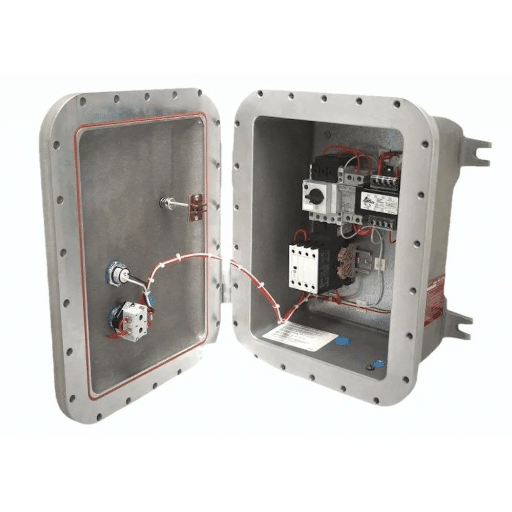
An explosion proof electrical enclosure is a sealed housing built to contain an internal explosion. It does not prevent sparks or arcs from igniting gas inside the box. Instead, it withstands the pressure and cools the escaping gases through machined flame paths so the external hazardous atmosphere cannot ignite.
This containment philosophy is the foundation of Class I, Division 1 protection under the U. S. National Electrical Code (NEC) and of Ex d or flameproof protection under IEC 60079-1 and ATEX.
The enclosure is hydrostatically tested to four times the maximum pressure expected from the specified gas mixture. Bolts, flanges, and cover joints are engineered so that hot gas loses heat as it escapes. That cooling drops the gas below the auto-ignition temperature of the surrounding fuel vapor before it reaches the atmosphere.
Key distinction: “Explosion proof” is the North American term. “Flameproof” is the IEC/ATEX term for the same containment concept. Both refer to Ex d protection.
Other protection methods serve different purposes:
- Ex e / increased safety: Prevents arcs, sparks, and hot surfaces by design. Used for terminal boxes, lighting, and low-energy components where internal ignition is not expected.
- Ex i / intrinsic safety: Limits electrical energy to levels too low to ignite gas. Common in instrumentation, sensors, and control circuits.
- Ex p / pressurization: Maintains clean air or inert gas inside the enclosure so flammable atmosphere cannot enter. Used for large control panels or analyzers.
- Ex t / dust ignition protection: Excludes combustible dust and limits surface temperature.
For gas stations, the most common choices are Ex d flameproof enclosures for high-energy equipment and Ex e increased safety enclosures for terminals and lighting circuits. For detailed information about Explosion-Proof Gas Station Equipment, please refer to our article about Explosion-Proof Gas Station Equipment.
Why Explosion Proof Enclosures Matter at Gas Stations
Gasoline vapor is heavier than air. It collects in low spaces, lingers around dispenser sumps, and can pool near vents, spill containment areas, and low wall packs. NEC Article 514 and NFPA 30A classify these locations as hazardous because flammable gas mixtures are present or likely during normal operation.
A standard NEMA 4X box is excellent at keeping rain out. It is not designed to contain an internal explosion. If a relay, switch, or terminal inside a NEMA 4X box arcs while gasoline vapor surrounds the enclosure, the flame can propagate through conduit openings, gasket gaps, or around the cover. The result is a fire that starts in the electrical system and spreads to the fueling area.
Mini-story: The Houston dispenser retrofit. In 2024, a contractor in Houston installed a NEMA 4X aluminum junction box inside a dispenser pit to save money on a retrofit. The box looked rugged and carried an IP66 rating, so the crew assumed it was suitable for the location.
During the final inspection, the Authority Having Jurisdiction (AHJ) flagged the installation. The pit beneath the dispenser is classified as Class I, Division 1, which requires an enclosure listed for that division.
The contractor had to remove the NEMA 4X box and install a Class I, Division 1 explosion proof junction box. He also added conduit seals within 18 inches of the enclosure and rerun bonding jumpers. The rework cost more than twice the original electrical budget. It also delayed the station opening by three weeks.
This story repeats on job sites around the world. The upfront cost of the correct enclosure is almost always lower than the cost of a failed inspection, rework, and lost revenue.
Hazardous Area Classification for Gas Stations
Before you can choose an enclosure, you must classify the space where it will live. Two systems dominate the market: the NEC Class/Division system used in North America and the IEC/ATEX Zone system used internationally. If you are not sure which certification you need, you can check out our article on ATEX vs IECEx vs UL.
NEC Article 514, Class/Division System
NEC Article 514 covers motor fuel dispensing facilities. Table 514.3(B)(1) defines classified locations around dispensers, tanks, and vents.
| Location | Typical Classification |
|---|---|
| Interior of dispenser pit or sump | Class I, Division 1 |
| Within 3 feet of an underground tank vent opening | Class I, Division 1 |
| Within 18 inches horizontally of a dispenser enclosure, up to grade | Class I, Division 2 |
| Up to 18 inches above grade within 20 feet horizontally of a dispenser | Class I, Division 2 |
| Canopy-mounted equipment above 18 feet | Usually unclassified or ordinary location |
Class I means flammable gases or vapors are present. Division 1 means they are present under normal operating conditions. Division 2 means they are present only under abnormal conditions, such as a leak or spill.
Gasoline vapors fall into Group D under the older NEC grouping or into Groups C and D depending on formulation. Hydrogen-rich atmospheres, including some alternative fuel sites, fall into Group B and require more severe protection.
IEC/ATEX, Zone System
IEC 60079-10-1 and ATEX use a zone model:
| Zone | Definition | Typical Gas Station Location |
|---|---|---|
| Zone 0 | Explosive atmosphere present continuously or for long periods | Inside fuel tanks, not normally accessible |
| Zone 1 | Explosive atmosphere likely during normal operation | Dispenser sump, vent outlets, seal leaks |
| Zone 2 | Explosive atmosphere not likely in normal operation and short-lived if it occurs | Vapor blanket around dispensers, low points |
Gasoline vapor is typically Group IIA or IIB. Hydrogen is Group IIC, the most severe group. Equipment marked IIC can also be used for IIA and IIB atmospheres.
NEC vs IEC/ATEX Comparison
| Attribute | NEC | IEC/ATEX |
|---|---|---|
| System basis | Class/Division/Group | Zone/Gas group/EPL |
| High-risk location | Class I, Division 1 | Zone 1 |
| Lower-risk location | Class I, Division 2 | Zone 2 |
| Containment method | Explosion proof | Ex d (flameproof) |
| Prevention method | Non-incendive / hermetic | Ex e (increased safety) |
| Common certification | UL, CSA, FM | ATEX, IECEx |
Rule of thumb: Equipment approved for a higher hazard level can be used in a lower hazard level, but not the reverse. Zone 1 equipment works in Zone 2; Zone 2 equipment does not work in Zone 1.
Protection Methods: Ex d, Ex e, Ex i, Ex p, Ex t
Choosing the right protection method is just as important as choosing the right hazard classification. Each method reflects a different engineering philosophy.
Ex d / Flameproof Enclosure
Ex d is the international name for the containment approach. The enclosure is strong enough to withstand an internal explosion and engineered so that escaping gases are cooled before they exit. Ex d is the default choice for high-energy equipment such as motor starters, transformers, large junction boxes, and disconnect switches in Zone 1 or Class I, Division 1.
Mini-story: The African mining depot. A project integrator in West Africa ordered standard Zone 2 control panels for a new fleet fueling island. The site plan showed the island as Zone 1 because fuel vapors were expected during normal dispensing. When the panels arrived, the local inspector rejected them because they carried only Zone 2 certification.
The integrator had to source new Ex db IIC T6 Gb explosion proof control panels, wait six weeks for delivery and IECEx documentation, and redesign the cable gland layout. The delay taught the team to confirm the zone classification before issuing a purchase order.
Ex e / Increased Safety
Ex e prevents ignition rather than containing it. The enclosure uses larger creepage and clearance distances, robust terminals, and controlled surface temperatures. It is lighter and less expensive than Ex d, but it is only suitable for equipment that does not produce arcs, sparks, or hot surfaces under normal operation. Common uses include terminal boxes, lighting fixtures, and low-energy control enclosures.
Ex i / Intrinsic Safety
Ex i limits the energy available in a circuit to a level below what is needed to ignite the specified gas mixture. It is used for instrumentation, sensors, and low-voltage control circuits. Intrinsically safe circuits often run through simple enclosures because the safety is built into the circuit design, not the box. Need to know the difference between Intrinsic Safety and Explosion-Proof? Please read our article about Intrinsic Safety vs Explosion-Proof.
Ex p / Pressurization
Ex p maintains a protective gas pressure inside the enclosure so a flammable atmosphere cannot enter. It is used for large control panels, analyzer houses, and equipment that would be impractical to build as Ex d. Ex p systems require purge controls, pressure monitoring, and alarms.
Ex t / Dust Ignition Protection
Ex t protects against combustible dust. While gas stations focus on vapor hazards, Ex t becomes relevant in adjacent grain handling, fertilizer storage, or bulk powder operations.
Protection Method Selection Table
| Application | Recommended Method | Typical Marking |
|---|---|---|
| Motor starter in dispenser pit | Ex d / explosion proof | Ex db IIB T6 Gb |
| Terminal box for lighting | Ex e / increased safety | Ex ec IIC T4 Gc |
| Tank level sensor circuit | Ex i / intrinsic safety | Ex ia IIC T6 Ga |
| PLC panel in analyzer shelter | Ex p / pressurized | Ex pxb IIB T4 Gb |
| Dust-handling equipment | Ex t / dust protected | Ex tb IIIC T135C Db |
NEMA, IP, and Certification Ratings Explained

Explosion protection and environmental protection are separate concepts. An enclosure can be explosion proof but rust out in a coastal climate. It can also be watertight and carry no hazardous location rating at all.
NEMA Ratings
| NEMA Rating | Meaning | Relevance to Gas Stations |
|---|---|---|
| NEMA 3 / 3R | Weather-resistant | Ordinary locations, not hazardous |
| NEMA 4 / 4X | Watertight and corrosion-resistant | Environmental protection only, not explosion proof |
| NEMA 7 | Explosion proof for Class I, Division 1, Groups A-D | High-energy equipment in hazardous vapor zones |
| NEMA 8 | Same as NEMA 7 for indoor/outdoor use | Rarely specified today |
| NEMA 9 | Dust-ignition-proof for Class II, Division 1, Groups E-G | Dust-handling adjacent operations |
Gas station enclosures are often dual-rated, such as NEMA 4X / 7, meaning they resist corrosion and contain internal explosions.
IP Ratings
IP codes describe ingress protection against solids and liquids.
| IP Rating | Solid Protection | Liquid Protection |
|---|---|---|
| IP54 | Limited dust | Splashing water |
| IP65 | Dust-tight | Low-pressure water jets |
| IP66 | Dust-tight | High-pressure water jets |
| IP67 | Dust-tight | Temporary immersion |
| IP68 | Dust-tight | Continuous immersion |
| IP69K | Dust-tight | High-temperature high-pressure washdown |
Most outdoor gas station enclosures should be at least IP66. Washdown areas or regions with heavy monsoon exposure may need IP67 or IP68.
Certifications and Standards
- UL 1203: U. S. standard for explosion-proof and dust-ignition-proof electrical equipment.
- UL 886 / UL 698: Enclosures for hazardous locations.
- CSA C22.2 No. 30: Canadian standard for explosion-proof enclosures.
- ATEX Directive 2014/34/EU: European framework for equipment intended for use in explosive atmospheres.
- IECEx: International certification scheme accepted in most global markets.
- IEC 60079-1: Flameproof enclosures (Ex d).
- IEC 60079-7: Increased safety (Ex e).
How to Read an Ex Marking
A typical marking reads Ex db IIC T6 Gb.
- Ex: Equipment for explosive atmospheres
- db: Flameproof protection, equipment protection level b for Zone 1
- IIC: Gas group covering hydrogen and acetylene
- T6: Maximum surface temperature 85 degrees C
- Gb: Suitable for Zone 1 gas atmospheres
For gasoline vapor, IIB T3 or T4 is usually sufficient. Hydrogen sites require IIC T6.
Materials and Construction
The enclosure material affects cost, weight, corrosion resistance, and thermal performance.
Aluminum Alloys
Aluminum is the most common material for explosion proof electrical enclosures. It is lightweight, machinable, cost-effective, and provides good heat dissipation. Most Class I, Division 1 junction boxes and control stations are cast aluminum. In inland, low-corrosion environments, aluminum can last for decades with basic maintenance.
Stainless Steel 304 and 316L
Stainless steel dominates in coastal, chemical, and high-washdown environments. Type 304 resists most atmospheric corrosion. Type 316L adds molybdenum for superior resistance to chlorides and salt spray. Stainless steel enclosures cost more upfront than aluminum, but their longer service life often produces a lower total cost of ownership in harsh locations.
Mini-story: The Florida coast. A retail operator on the Gulf Coast installed aluminum NEMA 4X boxes at a new station to reduce capital cost. Within three years, salt air and cleaning chemicals had degraded the coating and corroded the mounting feet. The covers no longer seated cleanly, and gasket compression became uneven.
The AHJ flagged the installation during a routine audit. The operator replaced the boxes with 316L stainless steel NEMA 7/4X explosion proof electrical enclosures and added quarterly gasket inspections. The upgrade cost more initially, but maintenance dropped and the station passed every subsequent inspection.
Cast Iron
Cast iron is heavy, durable, and historically common in heavy industrial applications. It remains in use for large motor terminal boxes and legacy systems but is less common in modern gas station design because of weight and handling challenges.
Glass-Reinforced Polyester (GRP)
GRP is lightweight and corrosion-resistant, making it attractive for offshore and chemical plants. However, GRP is generally not used for Ex d flameproof enclosures because it cannot reliably contain explosion pressure. It is more common in Ex e and Ex p applications.
Gaskets and Seals
Gaskets are the weakest link in any enclosure. Neoprene, EPDM, and silicone gaskets each have different temperature and chemical resistance profiles. A gasket that works well in a cold climate may harden and leak in a hot desert. Always match gasket material to the site environment and replace gaskets on a defined schedule.
How to Choose the Right Explosion Proof Electrical Enclosure

Selection becomes straightforward when you work through the variables in order. Here is a seven-step workflow.
Step 1: Classify the Hazardous Area
Use NEC Article 514 or IEC 60079-10-1 to define the zone around each piece of equipment. Mark Class I, Division 1 or Zone 1 locations first because they drive the most severe protection requirements.
Step 2: Identify Gas Group and Temperature Class
Match the fuel vapor to the correct gas group and auto-ignition temperature.
| Fuel | Common Gas Group | Minimum Temperature Class |
|---|---|---|
| Gasoline | IIB or D | T3 (200 degrees C) or T4 (135 degrees C) |
| Diesel | IIA or D | T3 |
| Hydrogen | IIC or B | T6 (85 degrees C) |
| Natural gas | IIA or D | T1 (450 degrees C) |
Choose a T-code with a maximum surface temperature below the auto-ignition temperature of the vapor.
Step 3: Select the Protection Method
Use Ex d for high-energy or arcing equipment. Use Ex e for terminals and lighting. Use Ex i for instrumentation. Use Ex p for large panels that cannot be built as Ex d.
Step 4: Match NEMA and IP Environmental Ratings
Add NEMA 4X or IP66 as a minimum for outdoor use. Increase to IP67/68 for immersion risk or IP69K for high-pressure washdown.
Step 5: Size for Components and Heat Dissipation
Internal components generate heat. A tightly packed enclosure can exceed its T-code under load. Leave adequate free volume, use heat sinks or breather drains where permitted, and verify the certified internal temperature rise.
Step 6: Verify Certifications for the Destination Country
North America typically requires UL or CSA listing. Europe requires ATEX notified body certification. Many Middle Eastern, African, and Asian markets accept IECEx.
Some countries require additional in-country registration. Confirm requirements before shipping equipment to the site.
Step 7: Plan Installation, Sealing, and Maintenance
Specify the correct cable glands, conduit seals, grounding lugs, and torque sequence. NEC Article 501 generally requires a conduit seal within 18 inches of a Class I, Division 1 enclosure entry. Document every installation detail for the AHJ and your maintenance team.
Common Gas Station Installation Mistakes
Even the right enclosure fails if it is installed incorrectly. These are the most common errors inspectors find.
Using NEMA 4X Where NEMA 7 Is Required
NEMA 4X stops water. It does not stop flame propagation. A NEMA 4X box in a Class I, Division 1 location is a code violation and a safety risk.
Skipping Conduit Seals
Seals isolate hazardous atmospheres inside conduit runs. NEC Article 501 typically requires seals within 18 inches of enclosure entries in Division 1 locations. Missing seals allow vapor to migrate through the raceway system.
Ignoring Low-Voltage Dispenser Disconnects
NEC 514.11 and 514.13 require disconnecting means for power and communication conductors serving each dispenser. Low-voltage circuits are often overlooked because they do not feel dangerous, but they can energize dispenser electronics during maintenance.
Mixing Ex d and Ex e Components
An Ex d enclosure must use Ex d cable glands and stopping plugs. An Ex e enclosure must use Ex e accessories. Mixing protection concepts voids certification.
Missing Grounding and Bonding Continuity
All metallic raceways, enclosures, and non-current-carrying parts must be bonded and grounded. A missing bonding jumper can create a static discharge path or raise touch potential during a fault.
Installing Ordinary Lighting in the Vapor Blanket
Canopy lights mounted 14 to 17 feet above grade are usually above the Class I, Division 2 boundary and only need wet-location ratings. Bollards, low wall packs, and under-canopy fixtures within 18 inches of grade and 20 feet of a dispenser must be hazardous-location rated, typically UL 844.
Using Unlisted Products
Counterfeit or non-listed enclosures slip onto some projects because they look similar to certified units. Always verify that the enclosure carries a valid UL, CSA, ATEX, or IECEx mark and that the mark matches the intended location.
Maintenance and Inspection Best Practices

Explosion proof electrical enclosures are not install-and-forget devices. Gaskets corrode, bolts loosen, and flame paths can accumulate debris.
Annual Visual Inspection Checklist
- Inspect enclosures for cracks, corrosion, and impact damage.
- Verify that all cover bolts are present and properly torqued.
- Check gasket condition and compression.
- Confirm that cable glands and stopping plugs are tight and correctly rated.
- Look for signs of water or vapor ingress.
- Review grounding and bonding continuity.
Gasket Replacement Intervals
Replace gaskets at least every three to five years in normal environments. In coastal, chemical, or high-temperature locations, inspect annually and replace every one to two years.
Flame-Path and Cover Torque Checks
After any cover removal, clean the flame path and reinstall the cover with the manufacturer-specified torque sequence. Uneven torque can distort the cover and compromise containment.
Corrosion Monitoring
Stainless steel still needs inspection. Chloride stress corrosion, galvanic corrosion between dissimilar metals, and coating failures can all degrade protection over time.
Documentation for AHJ Audits
Keep certificates of compliance, hazardous area classification drawings, installation records, and maintenance logs organized. Inspectors often request documentation before they request a physical inspection.
Integration with Shandong Shengrui Equipment
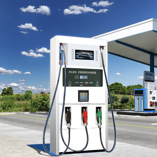
Explosion proof electrical enclosures work best when they are designed as part of an integrated station. At Shandong Shengrui Intelligent Equipment Co., Ltd., we supply certified enclosures as part of turnkey gas station packages that include fuel dispensers, explosion-proof barriers, storage tanks, piping, canopies, and skid-mounted stations.
Our engineering team works with project drawings to recommend the correct protection method, gas group, temperature class, material, and environmental rating for each location. We support OEM and ODM custom designs for unique site conditions, and we provide UL, ATEX, IECEx, and ISO 9001 documentation for global export projects.
When enclosures are selected alongside fuel dispensers, the entire fueling system aligns. The same principle applies to fire suppression systems. Need more information? You can check out our article on Explosion-Proof Fuel Dispensers.
It also applies to hydrogen safety equipment. A dispenser pit box, a canopy disconnect, and a fuel management control panel can all be specified from a single source with matching certifications and consistent technical support.
Conclusion
Explosion proof electrical enclosures are one of the smallest details on a gas station site plan, but they carry some of the largest safety implications. The right enclosure contains internal faults, protects the surrounding hazardous atmosphere, and keeps inspectors satisfied. The wrong enclosure turns a small electrical component into an ignition source.
Start by classifying your hazardous areas under NEC Article 514 or IEC 60079-10-1. Match each location to the correct gas group and temperature class. Choose Ex d for high-energy equipment, Ex e for terminals and lighting, and Ex i for instrumentation. Add the right NEMA and IP ratings for the environment, verify destination-country certifications, and plan installation with proper seals, glands, and grounding.
Key takeaways:
- Explosion proof enclosures contain internal explosions; they do not prevent them.
- NEC Class/Division and IEC/ATEX Zone systems describe the same hazards with different labels.
- NEMA 4X and IP66 are environmental ratings, not substitutes for explosion proof certification.
- Material selection should match the corrosive environment, not just the purchase price.
- Installation errors cause more field failures than product defects.
- Regular gasket, torque, and corrosion inspections protect long-term compliance.
If you are planning a new station or retrofitting an existing one, share your hazardous area classification drawings with our team. We will recommend certified explosion proof electrical enclosures that match your local code, your fuel type, and your long-term maintenance strategy.
Request a compliance review today and build your fueling infrastructure on a foundation that meets global safety standards.