The most expensive mistake in explosion-proof fuel dispenser procurement is not buying the wrong brand. It specifies a dispenser that passes factory inspection but fails field certification because one internal component lacks the correct explosion-proof rating.
When a contractor in Lagos installed four new dispensers at a high-volume fueling station, the ATEX-certified housings looked perfect. The state petroleum inspector opened one cabinet and found a payment terminal with no Zone 1 certification. Every dispenser had to be decommissioned. Replacement components cost $15,000. The station lost six weeks of revenue.
You already know that fuel dispensers operate in hazardous areas where gasoline vapors can ignite. What is harder is understanding which explosion-proof standards apply to each component inside the dispenser, how ATEX and UL requirements differ, and why a dispenser that is “certified” in one market may fail inspection in another.
This guide covers exactly that. You will learn what makes an explosion-proof fuel dispenser different from a standard unit, which certifications apply in Europe, North America, and international markets, how each internal component meets hazardous area requirements, and how to avoid the specification errors that delay projects and inflate costs. For a broader view of explosion-proof station equipment, see our explosion-proof gas station equipment guide.
What Makes a Fuel Dispenser Explosion-Proof?

An explosion-proof fuel dispenser is a dispensing unit engineered so that any internal ignition, such as an electrical arc from a relay, a spark from a motor brush, or heat from a display driver, cannot escape the housing and ignite the flammable vapor-air mixture surrounding the equipment. The term “explosion-proof” does not mean the dispenser survives an external blast. It means the dispenser contains an internal fault without propagating flames into the hazardous atmosphere outside.
Inside a dispenser cabinet, gasoline vapors collect near electrical components. Standard electronics can ignite this mixture through switching arcs or surface temperatures that exceed the fuel auto-ignition point. Explosion-proof engineering isolates these ignition sources through flame-path channels that cool escaping gases, vapor-tight gaskets that prevent ingress, and temperature-rated components that keep surface heat below the fuel ignition threshold.
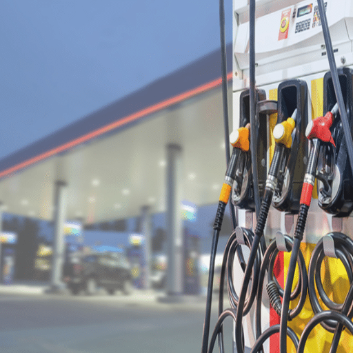
A fuel dispenser is the most complex explosion-proof device at any gas station. Unlike a junction box or a lighting fixture, a dispenser contains a meter, a pump motor, an electronic display, a payment terminal, vapor recovery valves, and dozens of cable glands and connectors, each requiring its own hazardous area certification. Understanding how these components integrate within a single flameproof housing is essential for correct specification.
The Fuel Dispenser Hazardous Area Map
Before you can select the right explosion-proof fuel dispenser, you must classify the hazardous zones around and inside the equipment. Two systems apply globally, and understanding both is critical for international projects.
Zone 1: Inside the Dispenser Cabinet
The interior of a fuel dispenser cabinet is classified as Zone 1 under the ATEX/IECEx system. This means an explosive atmosphere is likely during normal operation. Every electrical and electronic component inside the cabinet, from the flow meter sensor to the payment terminal display, must carry Category 2G protection (Equipment Protection Level Gb). In North American terms, this space is Class I, Division 1.
Zone 2: The Surrounding Dispenser Island
The area surrounding the dispenser, typically extending 0.5 to 1 meter from the cabinet and up to 1 meter above ground level, is classified as Zone 2. Here, an explosive atmosphere is unlikely under normal conditions but may occur briefly due to spills or leaks. Equipment in this zone requires Category 3G protection (Gc). In the US, this corresponds to Class I, Division 2.
Zone 0: Inside Underground Tanks and Vapor Lines
Inside underground storage tanks, submersible pump internals, and vapor recovery piping are Zone 0, where explosive atmospheres are present continuously. Equipment here requires the highest protection level, Category 1 (Ga). While the dispenser itself does not operate in Zone 0, its connection to underground tanks via piping and electrical conduit means the entire dispensing system must account for Zone 0 interfaces.
US NEC 514 Boundaries
The US National Electrical Code (NEC) Article 514 defines hazardous boundaries for motor fuel dispensing facilities differently from the zone system. Under NEC 514, the classified area extends 18 inches above grade and 20 feet horizontally from the dispenser. The space inside the dispenser cabinet is Class I, Division 1. The surrounding island area is Class I, Division 2. Above the canopy and beyond the 20-foot boundary is typically unclassified.
| Zone System | Area Definition | Typical Dispenser Location | Equipment Category |
|---|---|---|---|
| Zone 0 | Explosive atmosphere present continuously | Inside storage tanks, pump internals | Category 1 (Ga) |
| Zone 1 | Explosive atmosphere likely during normal ops | Inside dispenser cabinet | Category 2 (Gb) |
| Zone 2 | Explosive atmosphere unlikely, brief only | Dispenser island perimeter | Category 3 (Gc) |
| Class I, Div 1 | Gases present during normal operations | Inside dispenser cabinet | Equivalent to Zone 1 |
| Class I, Div 2 | Gases present under abnormal conditions | Dispenser island perimeter | Equivalent to Zone 2 |
For a complete understanding of how these classifications apply across all station equipment, see our hazardous area classification guide.
Key Explosion-Proof Standards for Fuel Dispensers
Fuel dispensers must comply with multiple overlapping standards depending on the target market. No single certification covers every jurisdiction, and understanding which standard applies to which component is essential.
ATEX Directive 2014/34/EU and EN 13617
In the European Union, ATEX Directive 2014/34/EU governs equipment design for explosive atmospheres. Fuel dispensers must carry ATEX Category 2G certification for Zone 1 operation. The ATEX Directive requires third-party assessment by a Notified Body for Category 2 equipment.
EN 13617 is the European standard specific to fuel dispensers. EN 13617-1 covers safety requirements, EN 13617-2 covers performance and metering accuracy, and EN 13617-3 covers vapor recovery. A dispenser sold in Europe must meet both ATEX (for explosion protection) and EN 13617 (for dispensing performance). These are complementary, not interchangeable, requirements.
IECEx Scheme and IEC 60079 Series
The IECEx scheme provides internationally harmonized certification based on the IEC 60079 series of standards. IECEx is recognized in over 50 countries and is often required alongside ATEX for international projects. For fuel dispensers, IECEx certification confirms that explosion-proof design meets the same technical requirements as ATEX but with global portability. The IECEx online certificate database allows buyers to verify any certificate in real time.
UL 1238 and UL 87A
In North America, two UL standards apply to fuel dispensers. UL 1238 covers control equipment for use in hazardous locations, including electrical components such as relay boards, power supplies, and control modules inside the dispenser. UL 87A specifically covers fuel dispensers as complete units. A fully compliant explosion-proof fuel dispenser for the US market typically needs both UL 87A listing for the overall unit and UL 1238 listing for individual control components. The UL 1238 standard and UL 87A standard are available from UL directly.
NFPA 30A and NEC Article 514
NFPA 30A, the Code for Motor Fuel Dispensing Facilities, and NEC Article 514 define installation requirements for dispensers in the US. These codes specify which hazardous location classifications apply to different areas of the station and mandate that all electrical equipment in classified areas be listed by a Nationally Recognized Testing Laboratory (NRTL). NFPA 30A is the primary reference for US fuel dispenser installations.
If you need to understand NFPA 30A Compliance, please read our article about NFPA 30A Compliance.
GB/T 3836 (China)
For equipment manufactured in China, the GB/T 3836 series defines explosive atmosphere requirements. GB/T 3836 is harmonized with IEC 60079, meaning Chinese-certified equipment can often achieve IECEx certification with minimal retesting. Export-oriented Chinese manufacturers, including Shandong Shengrui, typically hold dual CNEx/IECEx or CNEx/ATEX certifications.
| Standard | Scope | Market | Key Requirement |
|---|---|---|---|
| ATEX 2014/34/EU | Equipment for explosive atmospheres | EU (mandatory) | Category 2G for Zone 1 dispensers |
| EN 13617 | Fuel dispenser safety and performance | EU | Metering accuracy, vapor recovery |
| IECEx / IEC 60079 | International explosion-proof certification | 50+ countries | Harmonized with ATEX technical basis |
| UL 87A | Fuel dispensers | North America | Complete unit listing |
| UL 1238 | Control equipment in hazardous locations | North America | Component-level listing |
| NFPA 30A / NEC 514 | Installation requirements | US | Zone/classification boundaries |
| GB/T 3836 | Explosive atmosphere equipment | China | Harmonized with IEC 60079 |
Component-by-Component Explosion-Proof Requirements

A fuel dispenser is not a single certified device. It is a system of individually certified components housed within a flameproof enclosure. Understanding which component needs which certification is the key to correct specification.
Flow Meter
The flow meter measures every liter or gallon delivered. Most explosion-proof dispensers use positive displacement (PD) meters, though turbine and Coriolis meters appear in high-accuracy applications. The meter itself is typically mechanical and does not require electrical certification, but its sensor, the pulser that converts mechanical rotation into electronic signals, carries an intrinsic safety (Ex ib) or flameproof (Ex d) rating. Meter accuracy standards under EN 13617 and OIML R 117 require plus or minus 0.25% for retail dispensers and plus or minus 0.5% for commercial applications.
Submersible Turbine Pump (STP)
The submersible turbine pump sits inside the underground storage tank and pushes fuel up to the dispenser. The STP motor operates in Zone 0 and requires Category 1 (Ga) certification. In North America, UL-listed STPs for hazardous locations are standard. Suction pumps, which sit inside the dispenser cabinet and pull fuel from the tank, operate in Zone 1 and require Category 2 (Gb) certification. Flow rates range from 5 to 50 liters per minute for retail dispensers and 80 to 120 liters per minute for fleet applications.
Electronic Head and Display Unit
The electronic head controls the dispenser logic, managing presets, totals, and transaction data. The display unit shows fuel grade, volume, price, and transaction status. Both components sit inside the Zone 1 cabinet and require Category 2G certification. Modern dispensers use LED or LCD displays with low-power drivers to minimize internal heat, which helps maintain T6 temperature class compliance (surface temperature below 85 degrees Celsius). If you need to use explosion-proof electrical enclosures, please read our article about Explosion Proof Electrical Enclosures.
Vapor Recovery System
Stage I vapor recovery captures vapors during tank filling from delivery trucks. Stage II vapor recovery captures vapors during vehicle refueling. The Stage II vapor recovery components inside the dispenser, including vacuum pumps, valves, and sensors, operate in Zone 1 and require Category 2G certification. EN 13617-3 defines European vapor recovery requirements, while US requirements fall under EPA and state-level regulations.
Payment Terminal and POS Integration
Modern dispensers integrate payment terminals, RFID readers, and NFC modules directly into the electronic head. These components process transactions inside the Zone 1 cabinet and must carry individual explosion-proof certifications. Integrating consumer electronics into hazardous areas is one of the most challenging aspects of dispenser design, as payment terminals from standard commercial suppliers rarely carry ATEX or UL hazardous location listings. Dispenser manufacturers must either source certified terminals or design custom enclosures with Ex d or Ex ib protection for commercial components.
Cable Glands, Junction Boxes, and Internal Wiring
Every cable entry point into the dispenser cabinet requires a certified cable gland rated for the zone. Inside the cabinet, junction boxes and terminal blocks carry Ex e (increased safety) ratings. Wiring must be routed to prevent chafing, maintain separation distances, and avoid creating ignition paths between zones. These small components are frequently overlooked during specification, yet they are among the first items inspectors check.
Emergency Shut-Off Integration
Explosion-proof dispensers must integrate with station-wide emergency shut-off systems. The emergency stop (E-stop) circuit must be designed so that the switch itself does not become an ignition source in the hazardous area. This typically requires Ex d or Ex e rated E-stop stations connected to the dispenser control system. Integration with overfill prevention devices and leak detection systems completes the safety envelope. If you need to know about fire prevention measures at gas stations, please read our article on Fire Suppression & Emergency Shut-Off.
Protection Methods for Dispenser Components
Manufacturers achieve explosion protection inside dispensers through several engineering methods. Each method suits specific components and zones.
Flameproof Enclosure (Ex d)
The dispenser cabinet itself is a flameproof enclosure. If an internal arc ignites gas that has entered the cabinet, the housing withstands the explosion. Specially machined flame paths at door seams and cable entries cool escaping gases below the ignition temperature before they reach the outside atmosphere. Ex d is the primary protection method for the overall dispenser housing and for high-energy components like relay boards and power supplies.
Intrinsic Safety (Ex i)
Intrinsic safety limits electrical energy to levels below what is needed to ignite the gas mixture. Ex ib is one-fault-tolerant and suitable for Zone 1 components. Inside dispensers, intrinsic safety protects low-power sensors, pulser circuits, and communication lines. The flow meter sensor and temperature probes typically carry Ex ib ratings.
Increased Safety (Ex e)
Increased safety designs prevent arcs, sparks, and excessive surface temperatures under normal operation through tighter construction tolerances and better materials. Inside dispensers, Ex e protects terminal boxes, junction blocks, and cable glands. These components do not generate sparks during normal operation but must be engineered to prevent them under fault conditions.
Which Method for Which Component?
| Component | Protection Method | Zone | Typical Marking |
|---|---|---|---|
| Dispenser cabinet | Ex d (flameproof) | Zone 1 | Ex db IIB T6 Gb |
| Flow meter sensor | Ex ib (intrinsic safety) | Zone 1 | Ex ib IIA T4 Gb |
| Relay board / power supply | Ex d (flameproof) | Zone 1 | Ex db IIB T6 Gb |
| Display module | Ex d or Ex ib | Zone 1 | Ex db IIB T6 Gb |
| Payment terminal | Ex d or Ex ib | Zone 1 | Ex db IIB T6 Gb |
| Terminal blocks | Ex e (increased safety) | Zone 1 | Ex eb IIB T6 Gb |
| Cable glands | Ex e (increased safety) | Zone 1 | Ex eb IIB T6 Gb |
| STP motor | Ex d (flameproof) | Zone 0 | Ex da IIA T4 Ga |
| Vapor recovery valve | Ex d or Ex ib | Zone 1 | Ex db IIB T6 Gb |
ATEX vs UL Certification for Fuel Dispensers

The choice between ATEX and UL certification depends entirely on where the dispenser will operate. These schemes do not accept each other’s certifications.
European ATEX: Category 2G for Zone 1
European fuel dispensers require ATEX Category 2G certification, assessed by a Notified Body. The certification process involves design examination, prototype testing, and ongoing factory audits. ATEX-certified dispensers carry the Ex mark followed by the protection level, gas group, and temperature class, for example, Ex db IIB T6 Gb. ATEX certification for a new dispenser product line typically takes 12 to 18 months and costs 15,000 to 50,000.
North American UL: UL 87A and UL 1238
US and Canadian dispensers require UL listing. UL 87A covers the complete dispenser unit. UL 1238 covers control equipment used inside hazardous location enclosures. Both listings are required for full NEC compliance. UL certification involves design review, construction testing, and ongoing Follow-Up Services (factory inspections). UL listing for a dispenser product line typically takes 12 to 24 months and costs 20,000 to 60,000.
Dual Certification for Global Projects
Manufacturers serving both European and North American markets pursue dual ATEX + UL certification. Because ATEX and UL share the same technical foundation (IEC 60079), the marginal cost of adding a second certification is typically 20 to 30% more than a single certification. A manufacturer with IECEx certification can fast-track ATEX approval in 7 to 14 days when the ExTR (Test Report) and QAR (Quality Assessment Report) are ready.
A Middle East fuel retail chain expanding into both Germany and Saudi Arabia needed dispensers for 23 stations. Shandong Shengrui supplied ATEX Category 2G certified dispensers for Germany. For Saudi Arabia, IECEx-certified equivalents with the same housing and metering platform are shipped immediately. Using a common platform with different certification marks simplified procurement, reduced spare parts inventory by 40%, and ensured visual consistency across the entire portfolio. The dual-certification strategy added 25% to the initial certification budget but saved over $35,000 in avoided re-certification delays when the Saudi project expanded.
For a full comparison of certification costs, timelines, and geographic acceptance, see our ATEX vs IECEx vs UL certification guide.
Selecting an Explosion-Proof Fuel Dispenser: A Step-by-Step Framework
Choosing the right explosion-proof fuel dispenser requires matching certification, zone classification, gas group, and performance requirements to your specific station.
Step 1: Identify Your Target Market Certification
Determine which certification scheme your destination market requires. EU markets need ATEX. The US and Canadian markets need UL listing. Middle Eastern, African, and Asian markets often accept IECEx. If your project spans multiple markets, plan for dual certification from the start.
Step 2: Determine Zone Classification for Your Station Layout
Map the hazardous zones around your dispensers using either the ATEX zone system or the NEC class/division system. The dispenser cabinet interior is always Zone 1 / Class I, Division 1. The island perimeter is Zone 2 / Class I, Division 2. If your station layout includes unusual configurations, such as enclosed dispensing areas or below-grade installations, the zone boundaries may extend further.
Step 3: Match Gas Group and Temperature Class
Gasoline vapors fall under Gas Group IIA (ATEX/IECEx) or Group D (NEC) with a minimum temperature class of T3 (auto-ignition temperature approximately 280 degrees Celsius). Diesel requires Group IIA with T3 or T4. Ethanol blends may require reclassification to T4 due to lower auto-ignition temperatures. Hydrogen refueling requires the most demanding group, IIC, with T1 temperature class. Always verify that the dispenser certification covers the most dangerous fuel present at your station.
Step 4: Verify Meter Accuracy Class
Meter accuracy affects both regulatory compliance and revenue protection. EN 13617 and OIML R 117 require plus or minus 0.25% accuracy for retail dispensers. US weights and measures standards require similar tolerances. Verify that the dispenser’s metering system maintains accuracy within the certified temperature range.
Step 5: Evaluate Flow Rate vs. Station Throughput
Retail stations typically require 5 to 50 liters per minute per nozzle. Fleet fueling stations need 80 to 120 liters per minute. Undersized flow rates create queues and reduce throughput. Oversized flow rates may exceed nozzle and hose ratings. Match the dispenser’s certified flow rate to your station’s peak demand.
Step 6: Plan for Maintenance and Calibration Access
Explosion-proof dispensers require periodic calibration and component replacement. Accessing internal components means opening the flameproof enclosure. Plan for maintenance procedures that preserve the explosion-proof integrity of cable glands, gaskets, and flame paths. Dispensers designed with modular internal components simplify field service without compromising certification.
Common Explosion-Proof Dispenser Specification Mistakes
Ignoring Zone 1 Inside the Cabinet
Some buyers verify that the dispenser housing carries ATEX or UL certification but fail to check that internal components, payment terminals, displays, and cable glands carry individual Zone 1 ratings. Inspectors check every component inside the cabinet.
Specifying UL 87A Without UL 1238
UL 87A covers the dispenser as a complete unit. UL 1238 covers the control equipment inside. A dispenser with only UL 87A may fail inspection if internal control modules lack a separate UL 1238 listing.
Choosing the Wrong Temperature Class for Ethanol Blends
Gasoline vapors require a T3 temperature class. Ethanol blends have lower auto-ignition temperatures and may require T4. A Brazilian station that upgraded from E10 to E27 ethanol blend discovered this the hard way, spending $8,000 and three weeks re-certifying dispenser internals for the higher temperature class.
Neglecting Vapor Recovery Component Certification
Stage II vapor recovery components inside the dispenser, vacuum pumps, valves, and sensors carry their own hazardous area certification requirements. Treating the vapor recovery system as part of the “dispenser package” without verifying individual component certifications is a common oversight.
Undersizing Flow Rate
A fleet depot outside Accra installed four single-nozzle dispensers rated at 30 liters per minute. Their diesel trucks required 80 liters per minute minimum. Drivers waited 15 minutes per fill. The depot replaced all four units at full price, losing the initial savings entirely.
Integration with Station-Wide Explosion-Proof Systems

An explosion-proof fuel dispenser does not operate in isolation. It connects to underground storage tanks via piping and electrical conduit, links to automatic tank gauging and leak detection systems, integrates with emergency shut-off circuits, and coordinates with explosion-proof lighting for gas stations across the forecourt.
For turnkey station projects, skid-mounted stations offer pre-certified packages where dispensers, tanks, piping, and electrical systems arrive as an integrated, factory-tested unit. This approach eliminates field certification gaps between individual components and reduces commissioning time.
Emergency shut-off systems must connect to dispensers through explosion-proof circuits. The E-stop relay inside the dispenser cabinet must carry its own Ex d or Ex eb rating. Coordination with overfill prevention devices and leak detection ensures that a single safety event triggers a coordinated station-wide response.
2025-2026 Market and Technology Trends
The global fuel dispenser market reached approximately USD 2.8 to 3.2 billion in 2025 to 2026, with China producing roughly 60% of the world’s units. The explosion-proof equipment market as a whole is valued at USD 8.72 to 11.62 billion, with North America holding approximately 32% of global hazardous area equipment installations.
Several trends are reshaping explosion-proof dispenser design. Multi-fuel dispensers serving gasoline, diesel, ethanol, and hydrogen require IIC-rated components for hydrogen readiness, driving up certification complexity. Smart dispensers with IoT connectivity must integrate wireless communication modules into Zone 1 enclosures, a challenge addressed by the emerging IEC 60079-47 standard for wireless-enabled hazardous area fixtures.
ATEX and IECEx dual certification demand is growing at 8 to 10% annually as fuel retail chains expand across regulatory boundaries. LED-lit dispenser displays are reducing internal heat loads, making it easier to maintain T6 temperature class compliance. And payment terminal integration continues to push the boundaries of explosion-proof design as contactless, NFC, and mobile payment become standard expectations.
Frequently Asked Questions
Do all fuel dispensers need to be explosion-proof?
Yes. Every fuel dispenser operating in a classified hazardous area, which includes all dispensers at gas stations, must carry appropriate explosion-proof certification for the zone where it operates. In Europe, this means ATEX Category 2G. In North America, this means UL listing under UL 87A and UL 1238.
What is the difference between UL 87A and UL 1238 for fuel dispensers?
UL 87A covers the fuel dispenser as a complete unit. UL 1238 covers control equipment used inside hazardous location enclosures, such as relay boards, power supplies, and control modules. A fully compliant US-market dispenser typically needs both listings.
Can I use an ATEX-certified fuel dispenser in the United States?
No. ATEX certification is not recognized by US authorities. US installations require UL listing by a Nationally Recognized Testing Laboratory (NRTL). However, a manufacturer with ATEX and IECEx certification can pursue UL listing using the same technical documentation, reducing time and cost.
What gas group do I need for gasoline dispensers?
Gasoline vapors fall under Gas Group IIA (ATEX/IECEx) or Group D (NEC). This covers most standard gasoline and diesel applications. If your station also dispenses hydrogen, you need IIC-rated equipment, which is the most demanding group and covers all other groups by default.
Conclusion
An explosion-proof fuel dispenser is the most certification-intensive piece of equipment at any gas station. Unlike lighting or junction boxes, a dispenser contains a dozen individually certified components, from the flow meter sensor to the payment terminal, all housed within a single flameproof enclosure. Getting the specification right means understanding which standards apply (ATEX, UL 87A, UL 1238, EN 13617), which zone the dispenser operates in (Zone 1 inside the cabinet, Zone 2 at the island perimeter), and which gas group and temperature class match your fuel type.
The five key takeaways from this guide are:
- The dispenser cabinet interior is Zone 1, requiring Category 2G (ATEX) or Class I, Division 1 (NEC) certification for every internal component
- UL 87A and UL 1238 are both required for US-market dispensers, one for the unit, one for control equipment inside
- Component-level certification matters, payment terminals, displays, and cable glands each carry separate explosion-proof ratings
- Dual ATEX + UL certification adds only 20 to 30% marginal cost but opens both European and North American markets
- Fuel type determines gas group and temperature class, ethanol blends and hydrogen require higher ratings than gasoline
If you are specifying explosion-proof fuel dispensers for a new station or retrofit project, our engineering team can help you match the correct certification, zone classification, and performance requirements to your specific market and station layout. Contact Shandong Shengrui for dispenser specification support and custom certification guidance.