Ask five installers what size buffer tank a 12 kW heat pump needs. You will get 120 litres, 180, 240, 300, and “you don’t need one.”
All five can be right. That is the problem with heat pump buffer tank sizing: the market answers a calculation with folklore, and the folklore is inconsistent enough to look like disagreement.
It isn’t. Every published rule (10 litres per kW, 25, 100, two gallons per ton) comes from the same equation. Each one simply assumes a different run time and never says so.
This guide shows the formula underneath the rules, walks the sizing method with real numbers, and covers the cases where the correct answer is no tank at all. Along the way, you will meet the government test data most of the industry ignores, and one safety rule almost every consumer page gets wrong.
It sits inside our wider thermal store tank guide, which covers storage at commercial and industrial scale. If you already know your heat pump model and your smallest zone, the worked example below is the part you need.
What a Heat Pump Buffer Tank Actually Does
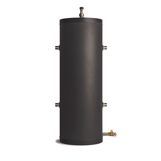
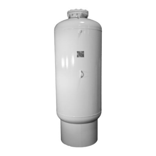
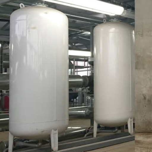
A buffer tank adds water volume to a heating circuit so the heat pump runs in longer, steadier cycles instead of switching on and off. It also separates the pump’s fixed flow from a zoned system’s variable flow, which is why it is sometimes called a low-loss header.
Three jobs get bundled into that description: volume, enough water that a cycle lasts several minutes; hydraulic separation, so the heat pump circuit and emitter circuit stop interfering; and defrost ride-through, where the tank carries the system while an air-source unit reverses to clear ice.
Notice what is missing. A buffer is not an efficiency device. The most thorough public testing of these tanks, a 2013 study commissioned by the UK government, found predicted COP differences between configurations were small enough that “the errors in the predictions probably outweigh the difference.” Buy a buffer to protect the compressor and stabilise delivery. Don’t expect your running costs to fall.
There is also a cheaper option most guides skip. A volumiser adds water volume without separating circuits. If all you need is volume, it is smaller, loses less heat, and needs no second pump. For the full distinction between these vessels and a thermal store, see our guide to thermal store vs buffer tank.
The One Formula Behind Every Heat Pump Buffer Tank Sizing Rule
Here is the equation. It is not proprietary, and it is not new.
V = 14.33 × Q × t ÷ ΔT
- V is the required total system volume in litres.
- Q is the net heat going into the tank while it charges, in kW.
- t is the run time you want, in minutes.
- ΔT is the temperature swing you will allow, in kelvin.
The constant 14.33 comes from water’s heat capacity: 1.163 watt-hours raises one litre by one kelvin, so 1000 ÷ (60 × 1.163) converts between litres, minutes, kilowatts and kelvin. Installers use a shorthand version: about 1.433 litres per kW per minute at ΔT 10 K.
Why the published rules disagree
Apply the formula at a fixed 10 K swing and ask what run time each published rule actually buys.
| Published rule | Equivalent L/kW | Run time at ΔT 10 K |
|---|---|---|
| 2–5 gal/ton (US commercial) | 2.2–5.4 | 1.5–3.8 min |
| 10 gal/ton (US hydronic) | 10.8 | 7.5 min |
| 10 L/kW (European ASHP) | 10 | 7.0 min |
| 15 L/kW (common minimum) | 15 | 10.5 min |
| 20 L/kW (residential) | 20 | 14.0 min |
| 25 L/kW (conservative) | 25 | 17.4 min |
| 50 L/kW | 50 | 34.9 min |
| 100 L/kW (Alpha-Innotec) | 100 | 69.8 min |
The spread is not a disagreement about physics but about purpose, and nobody wrote the purpose down. Ten litres per kW buys a seven-minute buffer. One hundred buys seventy, which is not buffering at all. That is storage, wearing a buffer’s name.
Cross-check against the government data
The same formula reproduces the published test data, which is the real test of whether it is right. The UK’s Department of Energy and Climate Change commissioned Kiwa to test buffer tanks on heat pumps. Their report gives a minimum system volume for a ten-minute cycle:
| Hysteresis | 2 kW | 4 kW | 8 kW | 16 kW |
|---|---|---|---|---|
| ΔT = 2 K | 143.5 L | 287.1 L | 574.2 L | 1,148.3 L |
| ΔT = 4 K | 71.8 L | 143.5 L | 287.1 L | 574.2 L |
Run 4 kW, 10 minutes, and 4 K through the formula, and you get 143.3 litres. The report says 143.5. The small gap is rounding in the constant.
That agreement matters practically: you can size from first principles instead of arguing about which rule of thumb applies. If you are sizing genuine storage rather than a buffer, our thermal storage tank sizing method takes the same approach further.
Heat Pump Buffer Tank Sizing, Step by Step
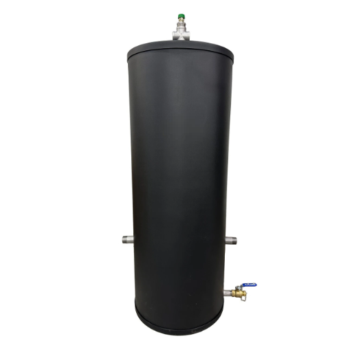
Four steps, and the fourth is the one that changes answers.
Step 1: Find the minimum output, not the nameplate. An inverter-driven heat pump modulates down to roughly 30% of rated capacity, so a 12 kW unit may idle at 4 kW. That minimum is what cycles, so it is what you size against. Manufacturer data sheets give it; if yours doesn’t, ask for it.
Step 2: Subtract the smallest load that can run alone. If one radiator or underfloor zone can call for heat by itself, that zone’s output is what the pump must shed. A 1 kW zone against a 4 kW minimum leaves 3 kW of surplus heat to absorb.
Step 3: Choose a run time and a swing. Ten minutes is a common target, with three to four starts per hour as the ceiling. A 2 to 4 K swing is realistic for low-temperature heating. Tighter swings need bigger tanks, fast.
Step 4: Calculate the total volume, then subtract what you already have. Pipework and emitters count. This is where a lot of buffers disappear.
Worked example: a 12 kW monobloc
Take a 12 kW unit with a 4 kW minimum output, a smallest zone of 1 kW, a 3 K swing and a 10-minute target.
V = 14.33 × (4 − 1) × 10 ÷ 3 = 143 litres of total system volume.
The property already holds about 40 litres in pipework and radiators. That leaves roughly 103 litres, so a standard 120 litre vessel covers it with margin.
Worked example: the retrofit that needs nothing
Now take a well-insulated retrofit with oversized radiators, the kind installers fit to let a heat pump run at low flow temperatures. Those radiators hold a lot of water.
In the Kiwa study, the assumed radiator volume at 4 kW was 176 litres against a minimum system volume of 143.5 litres at a 4 K swing. The required buffer is negative.
That is not a rounding artefact. It is the arithmetic saying the loop is already big enough. Measure your system volume before you buy a tank. Installers report removing buffers after tuning weather compensation and flow temperature, because the hardware was solving a problem the controls had already fixed.
Do You Need a Buffer Tank at All?
Four questions decide it, in this order.
- Is the heat pump inverter-driven? If it modulates, it cycles less, and the case for a buffer weakens considerably. The Kiwa report is direct: buffer tanks “are less relevant with inverter-driven heat pumps.” Fixed-speed units, especially air source, benefit most.
- How much water does the system already hold? Long pipe runs, large-diameter primaries and big underfloor loops all count. A 190 m² floor at 300 mm spacing can hold around 46 litres in pipe alone.
- Are TRVs fitted? Thermostatic radiator valves close and remove volume from the circuit, precisely when one room is calling, and the pump is most likely to cycle. This is the strongest practical argument for a buffer in an otherwise marginal system.
- Is it an air-source unit in a cold climate? Defrost cycles interrupt heat delivery, and a buffer carries the system through them. A manufacturer’s defrost volume, often quoted as 15 or 40 litres, is a different requirement from the anti-cycling volume. Confusing the two is one reason the numbers in circulation look inconsistent.
If the first two answers are favourable, a volumiser may be all you need. The MCS installation standard is often read as cautioning against unnecessary buffers, and that reading is usually right.
One more warning, from a real installation. A 9 kW unit was supplied instead of the specified 6 kW because the smaller model was out of stock. Their minimum outputs were 4.03 kW and 1.4 kW. On the same house, the buffer requirement roughly tripled. Oversizing the heat pump silently invalidates the sizing you did for the unit you specified. Standby loss is the cost of erring the other way: a 90 to 120 litre tank loses roughly 0.8 to 1.0 kWh per day.
For the full insulation and barrier method, see our guide to thermal storage tank insulation.
2-Pipe vs 4-Pipe: Choosing the Configuration
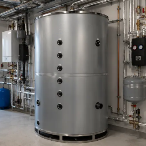
A 2-pipe connection uses the tank purely as extra volume. A 4-pipe connection adds hydraulic separation, at the cost of a second circulating pump and a tank that has to stratify properly to earn its keep.
| Configuration | What it adds | Main cost | Best for |
|---|---|---|---|
| 2-pipe, return | Volume only | No separation | Most domestic retrofits |
| 2-pipe, flow | Volume only | No separation | Where return tapping is awkward |
| 4-pipe | Volume plus hydraulic separation | Second pump; needs height to stratify | Multi-zone systems with different flow rates |
Much of the written advice recommends 4-pipe. The test evidence is more interesting.
Kiwa ran 63 tests across four configurations using 90 and 120 litre tanks on a 6 kW rig with one, four and seven radiators. The 4-pipe tank underperformed. The report’s explanation is specific: the tank “was too small for complete stratification and therefore became too well mixed,” and returning water “appears to bypass some of the water volume.” The 2-pipe-in-return arrangement produced the longest run times, because holding the return temperature down helps the heat pump.
Two caveats keep this honest. The tanks tested were small relative to the 6 kW rig, and the report says so. The fix it proposes is not “avoid 4-pipe” but to design the 4-pipe tank properly: taller rather than squat, baffled, ports positioned to discourage mixing and bypass, sensors placed deliberately, and the pump not running continuously.
Stratification is the mechanism behind all of that, and we cover it in our guide to thermal energy storage tank design. Wherever you put the tank, put it inside the heated envelope: heat lost from a buffer in a garage is heat lost from the building.
Vented vs Unvented: The Safety Rules That Apply
Here is where accurate quotation matters, because the market repeats a claim the regulation does not make.
Approved Document G requires a hot water system with a storage vessel to prevent stored water exceeding 100 °C and to discharge safely where it is visible. For unvented systems, paragraph 3.17 requires a minimum of two independent safety devices in addition to any thermostat: typically a non-self-resetting energy cut-out plus a temperature or combined temperature-and-pressure relief valve.
There is no size threshold. It applies to all unvented systems.
| Provision | What it actually says | What it does not say |
|---|---|---|
| 3.19 | Water heaters of 15 L or less with appropriate devices “will generally satisfy” G3(3) | That devices become mandatory above 15 L |
| Schedule 4 | Work on a vessel not exceeding 15 L is non-notifiable | That larger vessels need different devices |
| 3.17 | Two independent safety devices, all unvented systems | Nothing size-dependent at all |
The 15-litre figure means something else. It is a deemed-satisfaction route and a notification exemption, not a device threshold. Two further boundaries matter: systems up to 500 litres and under 45 kW should be a proprietary package to BS EN 12897 or BS 6700, and above that they are bespoke designs needing an appropriately qualified engineer.
Then there is the rule almost nobody quotes. Paragraph 3.35 says temperature relief valves and combined T&P valves should not be used in systems with no provision to automatically replenish stored water, for example, unvented primary thermal storage vessels. You need a second independent non-self-resetting energy cut-out instead.
That is the hinge between a domestic buffer and a commercial thermal store, and where the safety logic changes. Industrial-process systems fall outside G3(3) and sit under the Pressure Systems Safety Regulations 2000.
These are England and Wales requirements. Confirm the specifics with your local building control body, and check the equivalent code in your market.
Beyond the Buffer: Solar Diversion and Commercial Scale
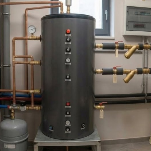
The same formula runs in both directions from a domestic plant room.
Solar diversion is sized by energy, not run time. If you are diverting surplus PV into a cylinder, size it for the energy you expect to capture:
V = E × 1000 ÷ (1.163 × ΔT)
Ten kilowatt-hours into a cylinder with a 45 K rise from cold mains gives about 191 litres. Buffers are sized in minutes; stores are sized in kilowatt-hours. That distinction explains most of the confusion in the L/kW rules. (Solar thermal collectors use a different basis again, which our guide to stratified hot water storage covers.)
Commercial scale keeps the method but changes the constraint. A buffer still protects the plant by extending run time, but the governing figure is no longer the nameplate. It is the first capacity step, the smallest stage that can run alone. Size against that, or you will size for a load the machine never sees.
Past a certain volume, you are no longer buying a buffer: the sizing basis switches from minutes to kilowatt-hours, and the economics change with it. Our guide to thermal storage tank cost covers that comparison.
Frequently Asked Questions
What size buffer tank do I need for a heat pump?
Use V = 14.33 × Q × t ÷ ΔT, where Q is minimum output minus the smallest zone load. For a 12 kW unit with a 4 kW minimum, a 1 kW zone and a 3 K swing over 10 minutes, that is about 143 litres of total system volume, less whatever the pipework holds.
Is 10 or 25 litres per kW correct?
Both, for different purposes. At a 10 K swing, 10 L/kW buys about seven minutes of run time and 25 L/kW buys about seventeen. Choose the run time you need, then calculate. Neither figure is wrong; neither is complete without its assumption.
Do I need a buffer tank with an inverter heat pump?
Usually less than with a fixed-speed unit. Inverter pumps modulate to roughly 30% of rated output, so they cycle less. A buffer still earns its place where TRVs close down most of the circuit, or where defrost needs covering.
What is the difference between a buffer tank and a volumiser?
A volumiser adds water volume only. A buffer adds volume and separates the heat pump circuit from the emitter circuit hydraulically. If you need volume alone, a volumiser is smaller, cheaper to run, and loses less heat.
Is 4-pipe better than 2-pipe?
Not automatically. In government testing, a 4-pipe tank underperformed a 2-pipe-in-return arrangement because the tank was too small to stratify and mixed instead. A properly designed 4-pipe vessel is a different proposition.
Does a buffer tank improve heat pump efficiency?
Treat that claim carefully. The best public testing found COP differences between buffer configurations were within model error. A buffer improves reliability and temperature stability, not efficiency.
Conclusion
Heat pump buffer tank sizing is one calculation, not a library of rules.
- Find the minimum output, not the nameplate. That is what cycles.
- Subtract the smallest zone load to get the heat the tank must absorb.
- Pick a run time and a swing, then apply V = 14.33 × Q × t ÷ ΔT.
- Subtract the volume you already have. The honest answer is sometimes zero.
- Quote the safety rules accurately. The 15-litre figure is not a device threshold.
The published rules aren’t competing. They’re the same equation with the assumption filed off. Once you can see the assumption, you can choose it deliberately instead of inheriting someone else’s. That is the whole of heat pump buffer tank sizing: pick the run time you want, then let the arithmetic pick the vessel.
For heat pump buffer tank sizing on a live project, send Shandong Shengrui your model, minimum modulation, smallest zone, and existing loop volume. We’ll return a sized vessel, a connection drawing, and the documentation your installer needs. If the arithmetic says you don’t need one, we’ll tell you that too. Speak with our engineers.