Daniel Mwamba had exactly six days before his 20,000L skid mounted fuel station arrived at a copper mine in Zambia. The supplier had sent drawings. The site crew had marked a flat spot near the haul road.
But no one had checked the soil bearing capacity, the anchor bolt pattern, or whether the local inspector required a separate lightning protection certificate. By the time the flat-rack truck arrived, the concrete pad was poured but still curing.
The crane could not reach the pad because of a drainage ditch that no one had considered. Daniel’s six-day buffer disappeared in one afternoon. His mobile fuel station installation guide had been a few WhatsApp messages and a handshake.
Daniel’s story is not unusual. Buyers often focus on capacity, price, and shipping, then treat installation as an afterthought. That mistake can add days or weeks of delay, failed inspections, and rework costs.
This mobile fuel station installation guide walks through every phase of installing a mobile fuel station. It starts the day you choose a site and ends the moment the first liter dispenses.
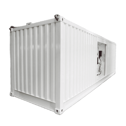
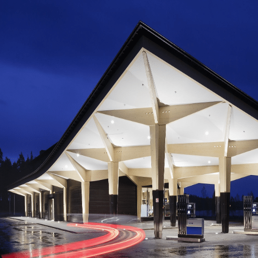
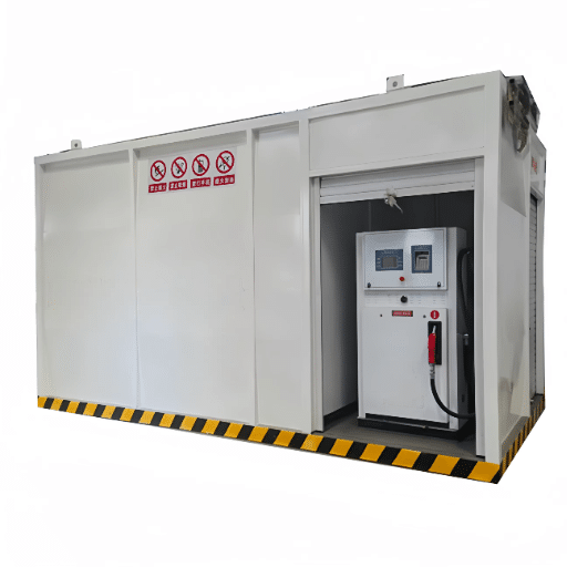
A mobile fuel station is any factory-built, transportable fueling system. Most units are either skid mounted fuel stations assembled on a steel frame or container fuel stations built inside a modified ISO box.
Both formats arrive with tanks, pumps, dispensers, and safety equipment pre-installed. Your job on site is to give that equipment a safe home, connect utilities, and prove it works before operation begins.
The global mobile fuel delivery system market research projects the sector will reach USD 5.8 billion in 2026. As demand grows, more project managers are installing these units for the first time. Getting the workflow right protects both the investment and the people who operate the station.
For detailed information about Skid Mounted Gas Station, please refer to our article about Skid Mounted Gas Station Solution.
What This Mobile Fuel Station Installation Guide Covers

This guide is written for project managers, site engineers, and buyers who need a practical workflow. It applies to skid mounted and containerized units. Some details differ by format. It also applies across regions; specific rules will always depend on your local authority having jurisdiction.
You will learn how to:
- Plan the site and permits before the unit leaves the factory.
- Prepare the foundation and utility routes.
- Receive, unload, and position the station safely.
- Connect piping, vents, and leak detection.
- Build a single integrated grounding and lightning protection system.
- Calibrate dispensers and commission the system.
- Document everything for final acceptance.
Think of installation as a partnership. The manufacturer builds and tests the equipment. The buyer prepares the site and manages local compliance. When both sides communicate early, the project stays on schedule.
Phase 1: Pre-Installation Planning and Permits
The most expensive installation problems start before the station arrives. A few hours of planning can save days of rework. This phase addresses the core mobile fuel station setup requirements that determine whether your project passes inspection on the first attempt.
Site Selection Requirements
Choose a location that balances operations, safety, and logistics. The station needs vehicle access for both delivery trucks and fueling vehicles. It also needs separation from ignition sources, buildings, and sensitive areas.
Common minimum separation distances vary by country, but typical guidance includes:
- Open flames or hot-work areas: 25–30 m
- General buildings and warehouses: 15 m
- Roads and highways: 8 m
- Overhead high-voltage lines: at least one pole height and 15 m horizontally
- Water sources, rivers, or wells: 100 m
Check local zoning as well. Some jurisdictions limit mobile stations to internal fleet use or temporary projects. Public retail usually requires additional licensing.
Chandra Patel managed a logistics yard outside Nairobi. He assumed a corner of the depot would work because it was close to the fleet parking. He did not notice the property line was only 6 m away.
The fire inspector rejected the location. The skid had to be repositioned before acceptance testing could begin.
Soil and Environmental Assessment
A mobile fuel station sits on a foundation that must carry the full loaded weight of the tank, fuel, dispenser, and refueling vehicles. Ground bearing capacity should be at least 10–20 t/m². Soft soil, loose fill, or seasonal flooding will require remediation.
Check the site for:
- Existing fill or buried debris
- Groundwater level and flood history
- Drainage patterns and slopes
- Soil corrosiveness, which affects grounding electrodes
Also, confirm that the site can shed spills. A slope of 1–2% away from the fueling area keeps rainwater and minor spills from pooling under the unit.
Permit Checklist
Before ordering, identify every approval you will need. Think of this as your mobile fuel station setup requirements checklist. Common requirements include:
- Planning or land-use permit
- Fire protection design review and acceptance
- Hazardous chemicals registration or filing
- Environmental impact assessment
- Lightning protection inspection certificate
- Electrical connection approval
Ask your supplier which certificates they provide, such as factory test reports, explosion-proof certificates, and calibration records. You will still need local permits, but manufacturer documents usually speed the process.
Phase 2: Site Preparation and Foundation
Once permits are clear, prepare the physical site. Proper mobile fuel station site preparation prevents the kind of delays Daniel Mwamba experienced in Zambia. While many principles apply to both formats, container fuel station installation has unique considerations for crane access and corner casting alignment. This section also focuses on the foundation and siting needs specific to skid mounted fuel station installation.
Placement Area Layout
Mark the footprint of the unit plus working space around it. The first step in mobile fuel station site preparation is marking the full footprint plus safe working clearance. Allow enough room for:
- Vehicle approach and turning radius
- Fuel truck unloading position
- Maintenance access on all sides
- Emergency egress routes
- Fire extinguisher and spill kit placement
Keep electrical panels, generators, and non-explosion-proof equipment outside the hazardous zone around dispensers and vents. That zone is typically defined by local code; GB 50156 and NFPA 30A code requirements both classify areas within approximately 3 m of fuel handling points as hazardous.
Foundation Design
Most skid mounted and container fuel stations sit on a reinforced concrete pad. The skid mounted fuel station foundation is usually a reinforced concrete pad sized to the unit’s footprint and anchor bolt pattern. The pad should be slightly larger than the unit footprint and designed by a local engineer for the actual load. Because the skid frame transfers concentrated loads to the pad, the skid mounted fuel station foundation must be designed by a qualified engineer for the actual bearing pressure.
Key targets:
- Ground bearing capacity: ≥10–20 t/m²
- Pad levelness: horizontal error ≤3 mm across the skid base
- Anchor bolts: positioned to match the supplier’s drawing exactly
- Surface finish: impermeable coating or sealant
The concrete itself should be cured before the station arrives. Green concrete can crack under load and will not hold anchor bolts reliably.
Containment is also required. NFPA 30A typically calls for secondary containment capacity of 110% of the largest tank. GB 50156 and related Chinese standards often specify 10–50% of tank volume, depending on local interpretation. Always confirm the rule that applies in your region.
Utility Trenches and Conduits
Run trenches for product piping, electrical conduits, and drainage before the unit arrives. Backfill with compacted material after pressure testing. Do not backfill piping before testing; leaks buried under soil are expensive to find and fix.
Slope the site at least 1–2% away from the fueling area. Provide a spill collection point or oil-water separator if required by local environmental rules.
Phase 3: Delivery and Unloading

The day the station arrives is not the day to improvise. Confirm the transport mode, lifting plan, and site access in advance.
Transport Mode Considerations
Skid mounted stations may ship flat-rack, break-bulk, RO-RO, or inside a standard container. Shipping logistics vary significantly by skid size and destination. For a detailed breakdown of flat-rack, container, and break-bulk methods with cost ranges and manufacturer tips, refer to our skid mounted gas station guide. Container fuel stations usually move as ISO boxes. Because the tank and equipment are enclosed, container fuel station installation requires careful attention to ventilation routing and door clearance. Each mode affects unloading:
- Flat-rack: usually requires a crane
- Break-bulk: crane or heavy forklift
- RO-RO: roll-off truck or trailer-mounted
- ISO container: container handler or crane with spreader
Verify lifting points and total weight with the supplier. Lifting by pipes, dispensers, or canopies can damage equipment and void warranties.
Unloading Checklist
Use this checklist when the truck arrives:
- Inspect the unit for shipping damage before it leaves the truck.
- Verify lifting points against the supplier drawing.
- Confirm the crane or forklift capacity exceeds the gross weight.
- Clear overhead power lines and obstructions.
Then lower the unit slowly onto the prepared pad. Check levelness with a spirit level or laser. Anchor the skid legs or container corners once level.
A standard skid mounted fuel station installation often takes 7–15 days from pad readiness to commissioning. Mini skids can be operational in hours. Large custom container stations may need up to 30 days if civil work and inspections are complex.
Phase 4: Mechanical and Piping Connections
With the unit positioned, connect it to the outside world. This phase includes product lines, vents, leak detection, and overfill protection.
Tank and Piping Installation
Connect the inlet or unloading line from the truck position to the tank. Install outlet piping to the dispenser. If the station includes vapor recovery, connect those lines as well.
Check every gasket and flange. Use oil-resistant nitrile gaskets at flanges. Confirm that breather valves and vents are clear and point away from ignition sources and buildings.
Install overfill protection devices. A high-level alarm and automatic shutoff at approximately 95% of tank capacity is standard practice. The unloading flow speed should be controlled, typically ≤0.71 m/s, to limit static electricity generation.
For buyers choosing between formats, our article on container fuel station vs skid mounted explains how piping access differs between enclosed containers and open skids.
Pressure and Leak Testing
Never skip testing. Even a small leak at a flange can become a major hazard.
| Test | Typical Requirement |
|---|---|
| Tank airtightness | 5–10 kPa, hold 30 minutes |
| Pipeline strength | 1.5× design pressure, minimum 0.2 MPa, hold 20 minutes |
| Leak verification | Soap bubble test plus combustible gas detector |
Pressure drop during the hold period should not exceed 5% of test pressure. If a leak appears, depressurize, repair, and retest before moving on.
Passing the pressure test is only the beginning. For the long-term monitoring and containment layers that protect your station after commissioning, see our complete guide to building a gas station leak prevention strategy.
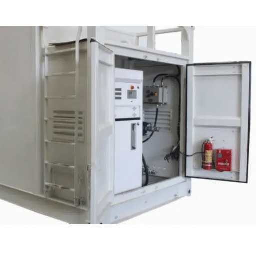
The type of tank matters here. Fuel storage tank options include single-wall, double-wall, and self-bunded designs. Double-wall and self-bunded tanks have interstitial leak detection that must also be tested and calibrated.
Phase 5: Electrical, Grounding, and Lightning Protection

Electrical work at a fuel station is not ordinary construction work. Every connection must prevent sparks and equalize electrical potential. This phase covers fuel station grounding and bonding, lightning protection, and hazardous-area electrical rules.
Power Supply
Confirm the voltage and phase required by the pumps and dispensers. Common supplies include 380V/220V AC or 12V/24V DC for smaller units. Use independent circuits with leakage protection. All electrical equipment in hazardous zones must carry the correct explosion-proof rating, such as Ex d IIB T4 or an equivalent local classification. Learn more about explosion-proof gas station equipment requirements for hazardous areas.
Grounding System
The single most important electrical decision is to use one common grounding grid for power system faults, lightning, and static electricity. A proper fuel station grounding and bonding design uses one integrated grid for all metalwork. Separate systems can create dangerous potential differences during a fault.
A typical grounding grid includes:
- A horizontal ring of 40×4 mm hot-dip galvanized flat steel around the station, buried at least 0.8 m deep
- Vertical electrodes of 50 mm galvanized steel pipe, 2.5 m long, spaced at least 5 m apart
- At least two separate leads from the grid to the unit’s grounding terminal box
- Target combined station resistance ≤4 Ω
In high-resistivity soil, use resistance-reducing agents, soil replacement, or an extended grid. Avoid corrosive chemicals that will attack the electrodes.
Equipotential Bonding
Every exposed metal part must be at the same electrical potential. Bond:
- Tank body to skid frame with flexible copper braid ≥16 mm²
- Flanges and valves with jumper wire ≥6 mm² when fewer than five bolts connect the flange
- Both ends of every metal pipe section
- Dispenser bases, pump motors, and enclosures with separate ground wires
- Unloading area static grounding post is interlocked with the pump
Never use series grounding for dispensers. Each unit needs its own dedicated path to the grid.
Before finalizing your electrical and grounding plan, verify that every safety system on site aligns with a complete gas station safety equipment checklist. That checklist covers fire suppression placement, spill kit accessibility, and emergency shutoff positioning—items that inspectors check alongside grounding resistance.
Lightning Protection
Lightning protection usually requires free-standing masts or rods, not just the container roof. Tie down conductors into the same common grid. Bond all metal fences, railings, canopies, and pipe trenches to the grid as well.
In Indonesia, a construction fleet skipped the integrated grid and used a separate lightning rod. A strike created a potential difference between the rod and the dispenser frame. The surge damaged the dispenser electronics and delayed commissioning until the grounding system was rebuilt.
Phase 6: Fuel Dispenser Calibration and System Commissioning
Mobile fuel station commissioning is the formal process of proving that every safety system, meter, and alarm performs as designed before the first commercial dispense. Commissioning proves that every safety system and meter works before customers or vehicles rely on the station.
Dispenser Calibration
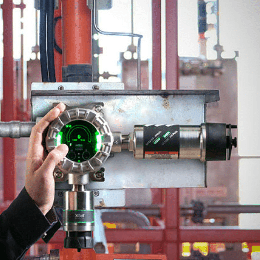
The fuel dispenser calibration procedure verifies that every meter reads within the allowed accuracy tolerance. Fuel dispensers must measure accurately. OIML R117 recommends accuracy within ±0.25% for commercial meters. Calibrate each dispenser against a certified measuring can. Record the readings and compare them to the meter display.
If the dispenser reads high, you give away fuel. If it reads low, you may violate weights-and-measures regulations. Following a documented fuel dispenser calibration procedure protects you from regulatory penalties and revenue loss.
Functional Tests
Test every safety function before the first commercial dispense:
- Emergency shutdown buttons at multiple locations
- High-level alarm and pump interlock
- Leak detection system alarm
- Static grounding alarm at the unloading point
- Fire detection or suppression system, if fitted
- Vapor recovery system airtightness, if required
Trial Run
Fill the tank under observation. Watch for leaks at flanges, valves, and fittings. Dispense a measured quantity and confirm meter accuracy. Record baseline values for tank level, pump pressure, and grounding resistance.
Those baseline readings become the foundation of ongoing monitoring. A modern fuel management system with automatic tank gauging turns initial records into real-time leak detection, inventory reconciliation, and automated compliance reporting.
A trial run is not the same as normal operation. Keep trained personnel on site, restrict vehicle access, and have fire extinguishers ready.
Phase 7: Documentation and Final Acceptance
The final phase is paperwork, but it is just as important as the concrete and piping.
Required Documents
Compile the following before the acceptance meeting. These documents are evidence that the mobile fuel station commissioning was completed correctly.
- Factory acceptance test report
- Equipment certificates and explosion-proof certificates
- Tank material certificates and non-destructive testing reports
- Calibration certificates for dispensers and instruments
- Pressure and leak test records with time-stamped readings
- Grounding resistance and continuity test reports
- As-built drawings and P&IDs
- Safety management procedures and emergency response plan
- Operator training records
Acceptance Meeting
Walk through the site with the inspector, supplier representative, and site manager. Rectify any deficiencies, repeat tests if needed, and sign the completion report. Only after acceptance should the station move into routine operation.
Understanding certification requirements for export markets helps buyers know which documents to request from Chinese manufacturers before shipment.
Common Installation Mistakes to Avoid
Even experienced contractors make these errors. Watch for them on your project:
- Pouring the pad without the supplier’s anchor bolt pattern. Every skid has specific bolt locations. Generic pads cause misalignment.
- Using separate grounding systems for power and lightning. One integrated grid is essential.
- Skipping pressure and leak tests. Visual inspection is not enough.
Other common errors include ordering before permits are clear and blocking maintenance access. Local rejections can strand an expensive unit. Tight clearances also make service and inspection difficult.
Installation Timeline and Budget Expectations
Budget and schedule depend on unit size, site complexity, and local inspection speed. Typical ranges are:
| Unit Type | On-Site Installation Time | Relative Cost vs. Equipment |
|---|---|---|
| Mini skid (1,000–5,000L) | A few hours to 2 days | 5–15% |
| Standard skid (10,000–30,000L) | 7–15 days | 15–30% |
| Large container station (30,000–60,000L+) | 15–30 days | 25–40% |
These figures exclude civil works, permits, and shipping. Turnkey installed costs, including all site work, can be two to four times the ex-factory equipment price.
Conclusion
A successful mobile fuel station installation guide is not just a checklist. It is a sequence of decisions. Those decisions start weeks before the unit arrives and end with signed acceptance documents.
Prepare the site and permits first. Build a foundation that matches the supplier’s drawings. Unload and level the unit carefully.
Connect piping, vents, and leak detection. Build one common grounding and lightning protection grid. Calibrate dispensers, test every safety system, and document every result.
The goal is simple: when the first vehicle pulls up to refuel, the station is safe, accurate, compliant, and ready.
If you are planning a mobile fuel station installation, request a project-specific installation guide from Shandong Shengrui Intelligent Equipment Co., Ltd. We will review your site conditions, local standards, and equipment specifications so your station arrives ready to install and commission without surprises.
Note: This guide provides general installation workflow guidance. Always follow local codes, manufacturer instructions, and qualified engineering review for your specific project.