Ignition rarely enters a fuel storage tank through its shell. It comes in through the vent. The flame arrester for fuel storage tank service is the device that stops it, which makes it the most consequential part bolted to the tank.
A tank can be certified, double-walled, barrier-filled, and sited to every requirement in the code. It’ll still vent to the atmosphere through a single hole in its roof. Everything that decides whether that hole is safe sits on top of it.
Those parts are the tank’s safety accessories: the flame arrester, the pressure/vacuum vent, the emergency relief vent, the submersible pump, the level gauge, and the grounding interlock. Most projects specify them late and one at a time, from whichever supplier is already quoting. That’s where compliant installations develop gaps.
Here’s the aim of this guide: closing those gaps. You’ll learn what each accessory does, which ones your product and site actually require, how they must be sized together, and what rating to write into a specification.
What you’ll learn:
- Why the vent path is one system, not a list of parts
- How to choose a flame arrester for a fuel storage tank
- What a pressure/vacuum vent does — and what it doesn’t
- Why submersible pumps and tank gauges carry different explosion-protection ratings
- How to select the full accessory package by hazard
For comprehensive information, please read our article on explosion-proof tanks.
The Vent Path Is One System, Not a Shopping List

Start with the part most buyers treat as an afterthought. A tank’s normal venting is a single flow path: vapour space → flame arrester → pressure/vacuum vent → atmosphere. Every element in that path adds resistance, and capacity is set by the total, not by any one device.
Three failures follow from ignoring this.
Undersizing collapses the tank. If the vent path can’t admit air fast enough during pump-out, the tank goes into vacuum and buckles inward. Practitioners call it a suck-in.
The classic case is a vent that’s adequate for normal transfer but far too small for the condensing steam in-breathing after a steam-out. That’s a routine maintenance operation, and it’s an event API 2000 doesn’t cover.
Fouling degrades capacity silently. Arrester elements clog with condensate, corrosion products, and polymerised residue, and nothing on the outside of the tank gives it away.
The tank looks normal while its relief path quietly shrinks. API 2000 addresses this directly: Section 3.5.2 notes that a blocked flame arrester compromises both overpressure and underpressure protection. Put plainly, the open vent is useless if the flame arrester is blocked.
Arrester pressure drop eats the vent margin. Vendors publish pressure-drop curves for clean conditions only, and those curves describe a freshly cleaned element. That’s why maritime practice, set out in IMO MSC/Circ.677, uses just 70% of a flame arrester’s rated performance in pressure-drop calculations. It’s a built-in allowance for fouling.
So size the arrester, the P/V vent, and the emergency vent against one calculation. Keep backpressure inside roughly 110% of the tank’s design pressure. And where a tank has no inert gas blanketing, consider two arresters, so one stays clear if the other fouls.
What safety accessories does an explosion-proof fuel tank need? A complete package has six parts: a flame arrester on the vent, a pressure/vacuum relief vent for normal breathing, an emergency pressure relief vent for the fire case, an Ex-rated submersible pump, an intrinsically safe level gauge, and a grounding interlock. Each is sized against the others.
Accessories are one layer of a wider system. See our guide to spill containment systems for the containment side.
Flame Arresters for Fuel Storage Tanks: Choosing the Right Type
A flame arrester is a passive device with no moving parts. Vapour flows through a matrix of narrow channels: crimped metal ribbon, wire mesh, or parallel plates. Any flame front passing through loses heat to the element until it drops below auto-ignition temperature and goes out. The gap between channels must be smaller than the vapour’s maximum experimental safe gap (MESG) for the flame to be quenched.
That single principle produces three distinct products.
| Type | Mounted | Stops | Typical use |
|---|---|---|---|
| End-of-line (EOL) | At the open vent outlet, facing atmosphere | External flashback entering the vent | Atmospheric and low-pressure fuel tanks, the default for a station tank |
| In-line deflagration | Inside a pipe run, between flanges | Subsonic deflagration travelling along the pipe | Vapour-return and gas-blanketing lines, short runs |
| In-line detonation | Inside a pipe run | Supersonic detonation plus deflagration, any pipe geometry | Long or obstructed runs where deflagration-to-detonation transition is credible |
How to choose, in order
- Where is the ignition risk? At the open vent, choose end-of-line. Along a pipe run, choose in-line.
- What is the vapour’s equipment group? Groups run from IIA (gasoline, diesel) through IIB to IIC (hydrogen). The element gap must be smaller than the vapour’s MESG.
- What flow capacity does the vent calculation require?
- How much pressure drop can the vent path tolerate?
- Does the application require an endurance-burn rating?
Two misconceptions cost buyers money. First, a Group IIA arrester won’t stop a Group IIC flame; the group must match the product, not the pipe size. Second, detonation rating isn’t a free upgrade. It suits long pipe runs and adds cost, and a deflagration-only arrester must never be used where a detonation can form.
What changed in 2024
The governing flame-arrester standard changed recently, and many supplier datasheets haven’t caught up. ISO/IEC 80079-49:2024, adopted in Europe as EN ISO/IEC 80079-49:2024, cancels and replaces ISO 16852:2016. The upper temperature limit rose from 150 °C to 200 °C, the working pressure range is 80–160 kPa, and the terminology shifted from “explosion group” to “equipment group”. If a certificate still cites ISO 16852, ask for the current edition.
In North America, UL 525 covers tank vent flame arresters of the deflagration type for petroleum and gasoline storage, plus in-line detonation arresters, with Section 22 addressing tank vent devices specifically. FM Approvals 6061:2022 classifies the same three applications described above.
Which certificate applies to which device is a subject in its own right. Our fuel tank certification guide maps it by region, and our maintenance guide covers cleaning intervals and element replacement.
Pressure/Vacuum Vents and Emergency Venting

Two devices keep a tank from bursting or buckling, and they handle completely different events.
A pressure/vacuum relief vent, often called a breather valve, manages normal breathing. It lets vapour out as liquid is pumped in or as vapour expands with daytime heat, and admits air as liquid is pumped out or vapour contracts overnight.
An emergency pressure relief vent handles the fire case. Sized on the tank’s wetted surface area, it releases vapour fast enough to stop the shell rupturing when contents are heated by an external fire.
Here’s the point that catches people out: a pressure/vacuum vent controls pressure and vacuum. It doesn’t stop flame propagation. The two functions live in different devices, which is exactly why the flame arrester sits on, or is combined with, the vent.
Sizing follows API 2000, which covers normal and emergency venting for aboveground liquid petroleum tanks from full vacuum to about 103.4 kPa (15 psig). The 6th edition, published in 2009, introduced the C-factor for in-breathing and the Y-factor for out-breathing; the 7th edition kept them. In practice, newer editions generally require more in-breathing capacity, so a sizing sheet prepared years ago may now be undersized.
Two rules stop the devices fighting each other. Sequence the set points: the emergency vent must open above the pressure at which the P/V vent is already flowing its rated capacity. And remember that what a modulating breather valve must pass is the larger of the maximum pump-in or pump-out rate. Not the sum, and not whichever number is easier to find.
Overfill protection is a related functional-safety device rather than a venting one. Our overfill prevention device guide covers valve types and testing schedules.
Grounding, Overfill and the Rest of the Stack
Static discharge during product transfer is a leading ignition cause at fuel facilities, and the fix is the cheapest accessory in the package. Bond the tanker to the tank shell, earth both, and fit an interlock that prevents the pump from starting until the bond is proven. This removes the ignition source rather than containing it, which is why it outperforms any rating on a nameplate.
Overfill protection is a functional-safety device certified to its own standard. EN 13616-1:2025 applies to overfill prevention devices on static liquid-fuel tanks, and it was added to the European harmonised list in 2025. It stops a fill before the tank overfills; it’s not a containment device and not a substitute for venting.
A few additions deserve a line each:
- Vapour recovery connections add backpressure to the vent path, so account for them in the sizing.
- Flame screens and weather hoods contribute their own pressure drop and must be included.
- Cathodic isolation matters wherever a coated tank is also grounded.
- Spill buckets and manholes form the interface between the tank and the containment system.
One honest point about barrier tanks. Internal explosion suppression acts on events inside the vessel. It doesn’t stop an external flashback entering the vent, and it doesn’t address overpressure.
Chinese barrier-fill technology is governed by AQ/T 3001-2021. That standard specifies the suppression material, and nothing more. It doesn’t exempt a tank from venting, flame arresters, or relief, so a barrier tank still needs its full accessory package.
Ex-Rated Pumps and Intrinsically Safe Gauges

The electrical half of the accessory package is where specifications most often go wrong, usually because the buyer copies a rating from one device onto another. The protection method isn’t a preference. It follows from how much energy the device puts into the hazardous zone.
A submersible turbine pump is flameproof. As an explosion-proof submersible pump, it contains a motor, so it brings real energy into the vapour space. The answer is to contain any internal ignition so it can’t escape: an Ex d enclosure, typically rated Ex d IIB T4 for fuel service.
A tank level gauge is intrinsically safe. As an intrinsically safe tank level gauge, the ATG probe sits inside the tank, in Zone 0. That’s the most hazardous classification, where an explosive atmosphere is present continuously. A flameproof enclosure is impractical there. Instead, the design limits the energy so a spark can’t occur at all: Ex ia, typically Ex ia IIB T4, fed through a certified intrinsically safe barrier.
That distinction explains the whole package, and it’s covered in more depth in our intrinsic safety vs explosion-proof comparison.
| Accessory | Function | Typical protection | Why |
|---|---|---|---|
| Submersible turbine pump | Moves product to the dispenser | Ex d IIB T4 (flameproof) | High-energy motor sits in the vapour space |
| Level gauge / ATG probe | Product, water and temperature measurement | Ex ia IIB T4 (intrinsically safe) | Operates in Zone 0; energy must stay below ignition |
| Magnetostrictive probe | Continuous level and leak-test data | Ex ia via an I.S. barrier | Same Zone 0 constraint; accuracy drives leak-test quality |
| Overfill prevention device | Stops the fill before overfill | Certified to EN 13616-1:2025 | A functional safety device, on its own standard |
| Static grounding interlock | Proves the bond before pumping | Interlock rather than an Ex rating | Removes the ignition source instead of containing it |
A specification that asks for an “explosion-proof level gauge” is asking for the wrong thing. What it needs is an intrinsically safe probe rated for the zone it sits in. Magnetostrictive probes commonly achieve level accuracy around ±0.3 mm and temperature accuracy around ±0.2 °C, which is what makes reliable leak testing possible in the first place. That’s a separate subject our automatic tank gauge leak detection guide covers in full.
Diesel and fleet applications add their own pump and monitoring requirements. See our explosion-proof diesel storage tank guide.
Selecting Tank Safety Accessories by Hazard
Work from the hazard, not the catalogue. The table below maps each risk to the device that answers it and the parameters to specify.
| Hazard | Device | Specify |
|---|---|---|
| External flashback at the vent | End-of-line flame arrester | Equipment group, flow capacity, maximum pressure drop, burn rating |
| Pressure or vacuum from transfer and thermal cycling | Pressure/vacuum relief vent | API 2000 in-breathing and out-breathing, sequenced set points |
| Fire exposure of the shell | Emergency pressure relief vent | Wetted-surface-area sizing, set point above the P/V vent’s full-flow pressure |
| Product transfer | Submersible turbine pump | Ex d IIB T4, capacity, dry-run protection |
| In-tank measurement | ATG or level probe | Ex ia IIB T4, accuracy, I.S. barrier, console compatibility |
| Static discharge during transfer | Grounding and bonding interlock | Bond-before-start logic, monitored earth continuity |
| Overfill | Overfill prevention device | EN 13616-1:2025, shutoff or alarm logic |
Applied to three common sites, the package looks like this. A retail forecourt with underground tanks needs an end-of-line arrester and P/V vent per tank, an Ex ia probe, and Ex d submersible pumps. That’s the standard configuration.
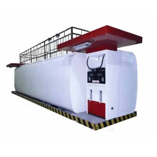
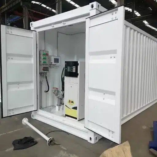
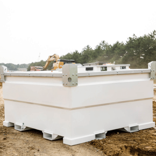
An aboveground diesel tank at a mine adds an emergency relief vent sized on the wetted area and Ex d pumps rated for the ambient conditions. A container or skid station concentrates all six devices into a small footprint, which makes the shared venting calculation essential rather than optional.
Request a specification pack for your site, and we’ll size the package against your product, zone, and throughput.
Frequently Asked Questions
What safety accessories does an explosion-proof fuel tank need?
Six: a flame arrester on the vent, a pressure/vacuum relief vent for normal breathing, an emergency pressure relief vent for the fire case, an Ex-rated submersible pump, an intrinsically safe level gauge, and a grounding interlock. Size them together, against one venting calculation.
Does a pressure/vacuum vent stop a flame?
No. A pressure/vacuum relief vent controls pressure and vacuum only. Flame protection comes from the flame arrester, which is why the two are installed together or supplied as a combined unit. Treating the vent as flame protection leaves the tank unprotected against external flashback.
End-of-line vs in-line flame arrester: what’s the difference?
An end-of-line arrester mounts at the open vent outlet and blocks external flashback from entering the vent. An in-line arrester mounts inside a pipe run and stops a flame travelling along the pipe. End-of-line suits atmospheric tanks; in-line suits vapour-return and blanketing lines.
Do I need a detonation-rated flame arrester on a tank vent?
Usually not. An open tank vent offers little pipe length for a flame to accelerate, so an end-of-line deflagration arrester is normally the correct choice. Detonation rating belongs on long or obstructed pipe runs, where a deflagration can transition to a detonation. Specify it only where the geometry requires it.
What is the difference between Ex d and intrinsically safe (Ex ia)?
Ex d, or flameproof, contains an internal ignition so it can’t escape the enclosure. It’s used for high-energy devices such as pumps with motors. Ex ia, or intrinsically safe, limits the energy so a spark can’t occur at all. It’s used for instruments in Zone 0. The rating follows the energy the device brings into the zone.
Why is my ATG probe intrinsically safe instead of explosion-proof?
Because it sits inside the tank, in Zone 0, where an explosive atmosphere is present continuously. A flameproof enclosure is impractical in that position and would not address the risk. An intrinsically safe probe with a certified barrier keeps energy below the ignition threshold, which is the correct solution for the zone.
Does a barrier (explosion-suppression) tank still need flame arresters?
Yes. Internal suppression answers an event inside the vessel. It doesn’t prevent an external flashback from entering through the vent, and it doesn’t protect against overpressure. A barrier tank requires the same vent, arrester, and relief package as any other atmospheric storage tank.
Conclusion: Specifications Are Systems
The accessory package decides whether a well-chosen tank performs as intended. Five points carry the logic:
- The vent path is one system. Size the arrester, P/V vent, and emergency vent against a single calculation.
- An arrester stops flame; a pressure/vacuum vent doesn’t. They do different jobs and are installed together.
- Fouling is the silent failure. API 2000 Section 3.5.2 recognises the blocked-arrester risk, and IMO practice derates rated performance to 70% for pressure-drop work.
- Protection method follows energy. Ex d for powered devices, Ex ia for instruments sitting in Zone 0.
- A barrier tank still needs the full package. Suppression inside the vessel doesn’t answer external flashback or over-pressure.
Work through the hazard table above, confirm the current standard editions on every datasheet, and check that your flame arrester for the fuel storage tank matches your product’s equipment group rather than your pipe size. Those three checks prevent most accessory failures before they reach site.
Specifying the accessory package alongside the tank, from one supplier, removes the gaps that open when six devices arrive from six vendors. Tell us your product, zone, and throughput, and our engineering team will size a matched package. Request a quote or review our explosion-proof tank range to start.